Rear Transition Module: Face Plate
10007175-02 KAT4000 User’s Manual
13-5
FACE PLATE
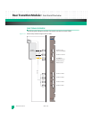
The rear face plate includes openings for six 9-pin micro-D connectors and one RJ45 con-
nector for serial I/O (see
Fig.13-1). There are also two reset switches: a board reset and an
IPMI reset.
CONNECTORS
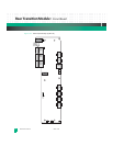
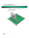
There are several connectors on the KAT-Z3DB (see Fig. 13-2). Descriptions and pin assign-
ments are listed below.
Console Serial Ports
There are multiple asynchronous console serial ports on the face plate. P1 is for the host
serial port, P2 is for the fat pipe serial port, and P4-P7 are for AMC sites 1-4. These ports
operate at EIA-232 signal levels, but do not provide any handshaking functionality. The con-
nectors for the console ports are micro-DB9 connectors, with the following pin assign-
ments.
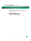
Table 13-2: Console Serial Port Pin Assignments, P1, P2 and P4-P7
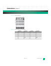
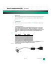
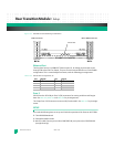
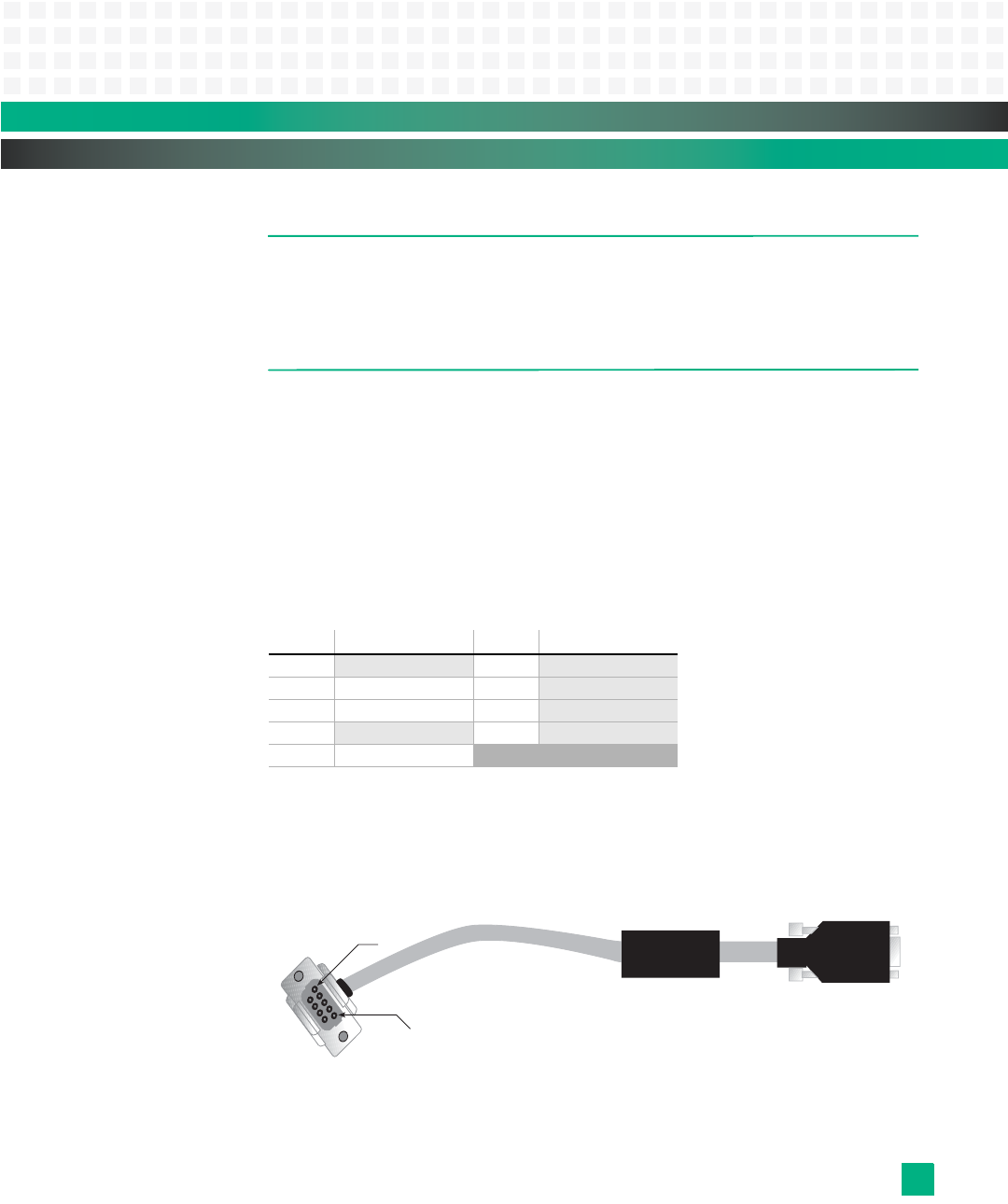
The standard Emerson console cable (#10007665-xx) is cross-pinned, as shown in Fig. 13-4.
A straight-through 9-pin cable (#10007664-xx) also is available.
Figure 13-3: Micro-D Console Cable
Pin: Signal: Pin: Signal:
1 no connect 6 no connect
2 RXD (Data In) 7
no connect
3 TXD (Data Out) 8
no connect
4
no connect 9 no connect
5 ground
Pin 1
Pin 5
Micro D
Connector
Ferrite
DB9
Connector


