Setup: KAT4000 Circuit Board
KAT4000 User’s Manual 10007175-02
2-4
Front Panel
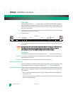
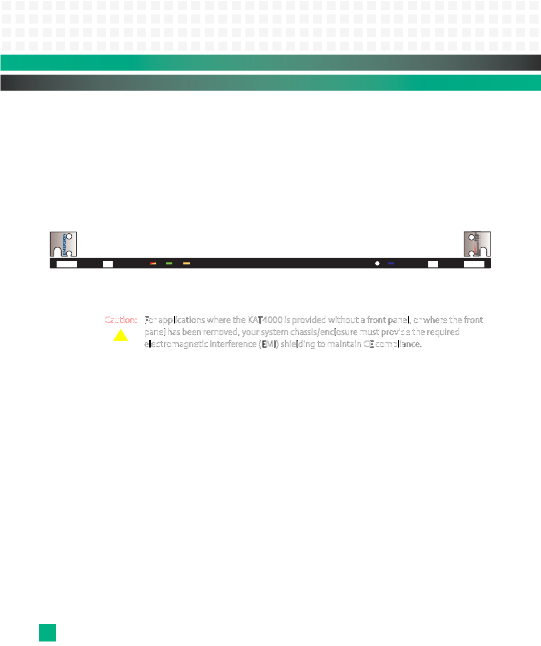
The front panel, shown in Fig. 2-3, consists of four single-width, mid-size Advanced Mezza-
nine Card (AMC) sites (double-width and compact modules can be accommodated), a hot
swap LED, an out of service LED, two user LEDs (see “LEDs” on page 2-10 for more informa-
tion), and a reset switch.
Note: When using a compact AMC module, the module must have a front panel that fully covers the front opening
of the KAT4000 to maintain EMC compliance.
Figure 2-3: KAT4000 Front Panel
Note: The electromagnetic compatibility (EMC) tests used a KAT4000 model that includes a front panel assembly
from Emerson.
Caution: For applications where the KAT4000 is provided without a front panel, or where the front
p
anel has been removed, your system chassis/enclosure must provide the required
e
lectromagnetic interference (EMI) shielding to maintain CE compliance.
Connectors
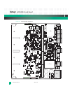
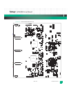
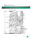
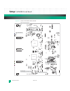
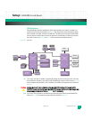
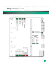
The KAT4000 circuit board has various connectors (see Fig. 2-1), summarized as follows:
EIA-232: A serial port is accessible off of the CPU through an on-board header for development pur-
poses and routes to Zone 3.
Ethernet: A 10/100 Ethernet port is accessible off of the CPU through Zone 3.
AMC Expansion Sites J1-J4:
Each site is capable of supporting an AMC module, depending on the configuration, using
B+ style AMC connectors. J1-J4 map to sites B1-B4 (see
Table 8-1 for pin assignments).
Backplane Connectors: Whether individual backplane connectors are populated on the KAT4000 depends on the
specific product configuration. PICMG 3.0 specification defines three connector zones on
the backplane:
• Zone 1 is the power connection (dual redundant -48V DC) and system management
connections—P10
• Zone 2 is the data transport interface covering: Base, Fabric, and Synchronization clock
interfaces—J20 through J24
Front Panel
KAT4000
OOS
2
3
H/S
B1
B2
B3
B4
Out of service
and user LEDs
Hot
Swap
LED
AMC1 AMC2 AMC3 AMC4
RST
Reset
Switch
!


