System Management: IPMC Overview
KAT4000 User’s Manual 10007175-02
9-2
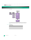
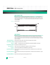
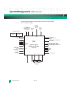
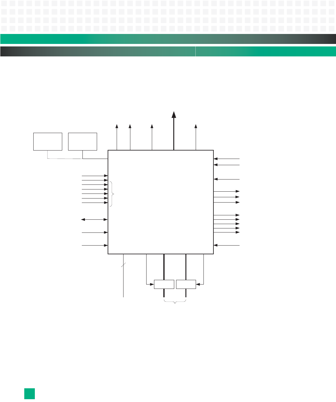
The following block diagram shows the IPMC connections for the KAT4000.
Figure 9-1: IPMC Connections Block Diagram
IPMB-B
IPMB-A
IPMC
Pigeon Point
Reference Design
Front
Panel
LEDs
Hot Swap Switch
IPMC Debug
Console
IPMC Reset
Switch
Boot
Device
Select
Payload
Reset
Temperature Sensors
IJ
IPMB-0
ShMC Present
(from JP7)
CPU Present
AMC Sites (B1-B4):
Ready,
Payload Power Current Monitor
RTM: Payload Power Enable
RTM: Management Power Enable
Payload
Power Enables and
AMC Sites (B1-B4):
Management
RTM: Present
AMC Sites (B1-B4): Enable
Payload
Processor
Interface


