


CPLD: JTAG Interface
10007175-02 KAT4000 User’s Manual
7-19
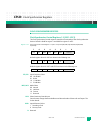
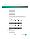
HPI, PPI: Holdover and PLL Lock Loss Pending Interrupt (read-only)
1Interrupt latched
0 No interrupt latched
HS, PS: Holdover and PLL Lock Loss Status (read-only)
1 Indicates synchronizer in holdover/PLL lock loss state
0 Indicates synchronizer not in holdover, PLL locked
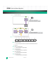
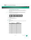
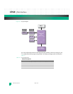
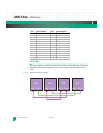
JTAG INTERFACE
The KAT4000 provides a single 10-pin JTAG header (JP3) for in-system programming of on-
board PLDs, as well as Altera PLDs on AMC site 1 (see
Fig. 7-2). The header pin assignments
are defined in
Tab le 7 - 2.
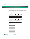
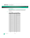
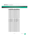
Table 7-2: JP3 PLD JTAG Pin Assignments
Pin: Description: Pin: Description:
1 Test Clock Input (TCK) 2 ground 1
3 Test Data Output (TDO) 4 3.3 volts VCC
5Test Mode Select (TMS)6
not connected
7
not connected 8 not connected
9 Test Data Input (TDI) 10 ground 2