


Monitor: Basic Operation
KAT4000 User’s Manual 10007175-02
14-4
This prompt is also displayed as an indication that the monitor has finished executing a
command or function invoked at the command prompt (except when the command loads
and jumps to a user application). The hardware product name, KAT4000, and the current
software version number are displayed in the prompt.
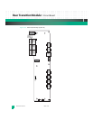
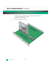
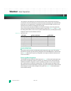
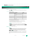
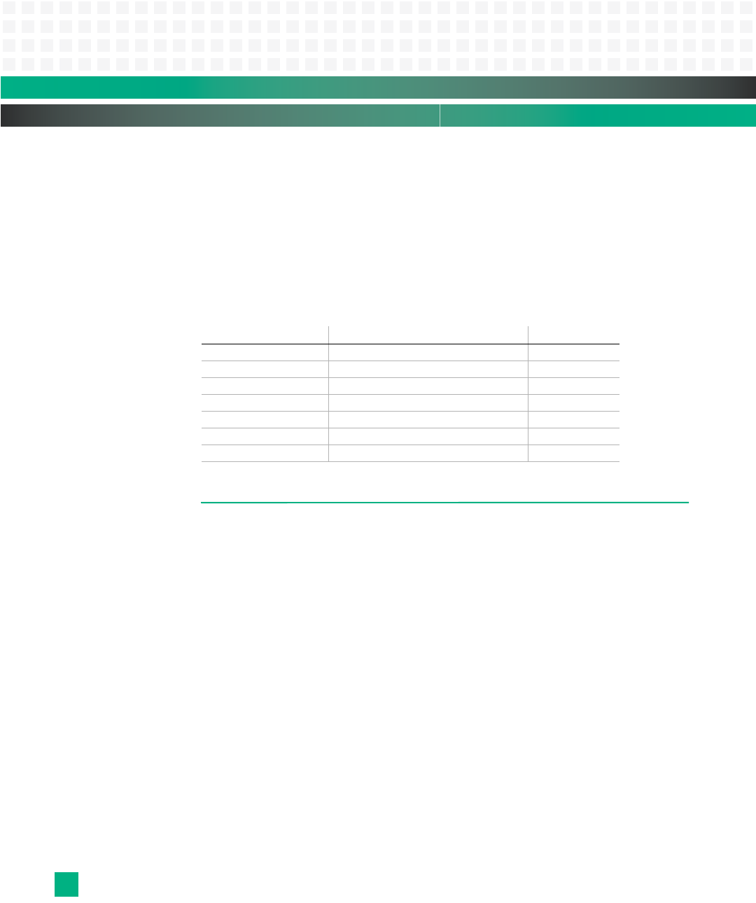
Prior to the console port being available, the monitor will display a four-bit hexadecimal
value on LED1 through LED4 to indicate the power-up status (see
Table 14-1). See Fig.2-7 for
the debug LED locations. In the event of a specific initialization error, the LED pattern will be
displayed and the board initialization will halt.
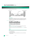
Table 14-1: Debug LED Codes
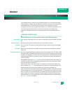
BASIC OPERATION
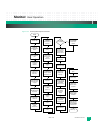
The monitor performs various configuration tasks upon power-up or reset. This section
describes the monitor operation during initialization of the KAT4000 board. The flowchart
(see
Fig.14-3) illustrates the power-up and global reset sequence (bold text indicates envi-
ronment variables).
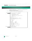
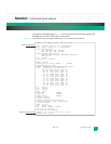
Power-up/Reset Sequence
The KAT4000 monitor follows the boot sequence in Fig. 14-3 before auto-booting the oper-
ating system or application software. At power-up or board reset, the monitor performs
hardware initialization, diagnostic routines, autoboot procedures, free memory initializa-
tion, and if necessary, invokes the command line. The U-Boot monitor also detects if the
optional PCI Express and serial Rapid I/O switches are present. Note that the U-Boot monitor
has the ability to timeout while waiting for PCIE_WAIT. See
Table 14-6 for default environ-
ment variables settings.
LED Code: Power-up Status: LED Value:
BOARD_PRE_INIT start booting, setup BATs done 0x01
SERIAL_INIT console init done 0x02
CHECKBOARD get processor and bus speeds done 0x03
SDRAM_INIT RAM / ECC init done 0x04
AFTER_RELOC U-Boot relocated to RAM done 0x05
MISC_R final init including Ethernet done 0x06
GONE_TO_PROMPT — 0x00