Rear Transition Module: Functional Overview
KAT4000 User’s Manual 10007175-02
13-2
FUNCTIONAL OVERVIEW
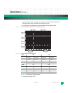
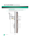
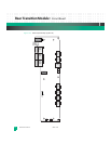
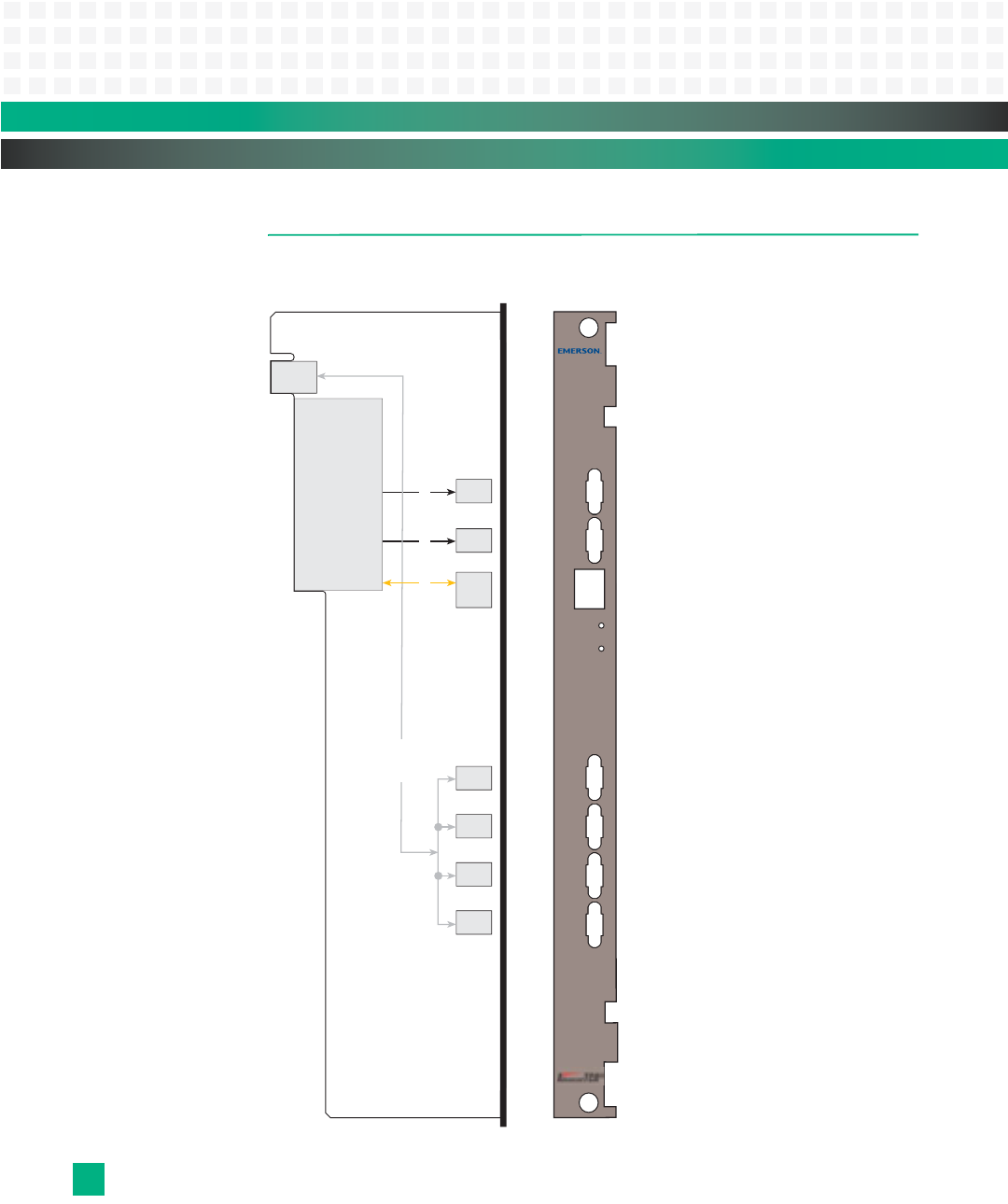
The following block diagram provides a functional overview for the KAT-Z3DB.
Figure 13-1: RTM General System Block Diagram with Face Plate
User I/O
EIA-232 10/100 PHY
SER
FP
SER
Host
Enet
Board Reset
IPMI Reset
SER
AMC4
SER
AMC3
SER
AMC2
SER
AMC1
KAT-Z3DB
10/100BASE-T
Debug Ethernet Port
Serial Port to the
Fat Pipe Switch Module
Serial Port to the CPU
Board Reset Switch
IPMI Reset Switch
Serial Port to AMC4
Serial Port to AMC3
Serial Port to AMC2
Serial Port to AMC1


