Central Processing Unit: Processor Reset and Clocking Signals
KAT4000 User’s Manual 10007175-02
3-12
Local Bus Controller (LBC)
The MPC8548 LBC connects to external memory, DSP and ASIC devices. There are three
separate state machines:
• General-Purpose Chip Select Machine (GPCM) controls access to asynchronous devices
• User Programmable Machine (UPM) interfaces synchronous devices
• The Synchronous DRAM (SDRAM) controller provides access to standard SDRAM
Chip Select Generation
The MPC8548 memory controller functions as a chip select (CS) generator to access on-
board memory devices, saving the board’s area which results in reduced cost, power con-
sumption, and increased flexibility.
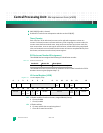
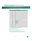
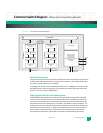
Tab le 3 - 4 lists the chip selects for the KAT4000 module.
Table 3-4: MPC8548 Chip Select
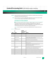
2. Jumper selectable (see “Jumpers” on page 2-5 for jumper options).
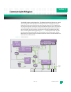
PROCESSOR RESET AND CLOCKING SIGNALS
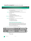
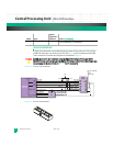
The MPC8548 external reset and clocking signals include:
HRESET*: Hard Reset input completely resets the MPC8548 and causes a power-on reset (POR)
sequence.
HRESET_REQ*: Hard Reset Request output causes internal block requests that HRESET* be asserted. This
can be requested by a hardware device, for example a watchdog timer event.
SRESET*: Soft Reset input causes a machine check interrupt assertion to the e500 core to undergo its
soft reset sequence.
READY: Ready output means the MPC8548 has completed the reset operation and is not in a
power-down (nap, doze, or sleep) or debug state.
Select: Assignment:
CS0* Boot (Socketed or NOR Flash)
22
CS1* Flash 0
CS2* Flash 1
CS3* Socketed Flash
CS4* KSL Programmable Logic Device (PLD)
CS5* NAND Flash
CS6* Ethernet Core Switch
CS7* Fat Pipe


