Fat Pipe Switch Module: 10 GbE-1 GbE Fat Pipe Switch Module
10007175-02 KAT4000 User’s Manual
5-11
10 GBE-1 GBE FAT PIPE SWITCH MODULE
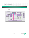
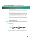
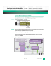
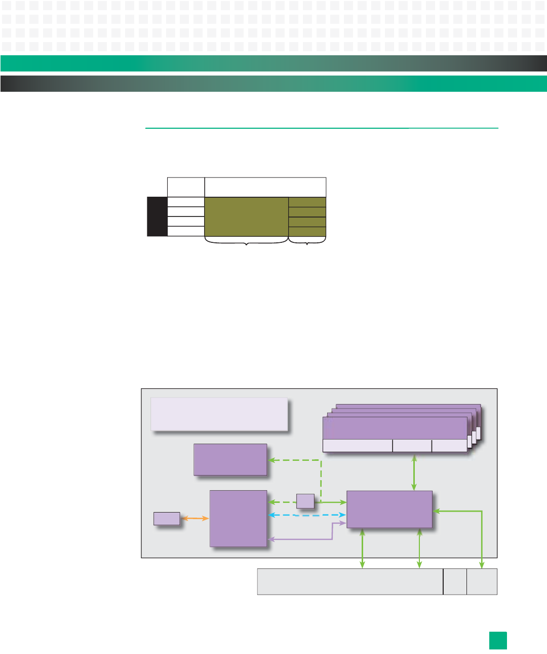
Fig. 5-8 shows how the 10 GbE-1 GbE fat pipe switch module maps to ports defined by the
AMC.0 specification; see
Fig. 1-3 for the full port mapping diagram.
Figure 5-8: AMC Port Map Fat Pipes Region–10 GbE-1 GbE
Fat Pipes: This region supports data path connections such as GbE. It can carry large amounts of data
without significantly degrading the speed of transmission.
x4: This refers to the link width of the port (the number of lanes that can be used to intercon-
nect between two link partners).
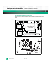
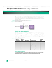
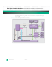
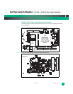
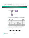
The following diagram shows the implementation of the 10 GbE-1 GbE fat pipe switch
module on the KAT4000:
Figure 5-9: Signal Routing of the 10 GbE-1 GbE Fat Pipe Switch Module on the KAT4000
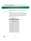
Port Mapping
Port #
Basic
Connector
MPC8548
Processor
RGMII
4
Fat Pipe Switch Module
10 GbE-1 GbE
AMC (x4) Single Wide,
Half/Full/Extended Height
I
2
C
Fat Pipe
Local bus
GbE
10 GbE
PCIe (x1)
10 GbE
10 GbE
GbE*
GbE
PHY
VSC7376
Ethernet Core Switch
Layer 2
(Optional)
Base High Speed
Fabric A
Clock RTM I/O
(Optional)
High Speed
Fabric B
J20 Zone 3J23


