AMC Sites: AMC Connectors
KAT4000 User’s Manual 10007175-02
8-2
AMC CONNECTORS
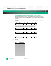
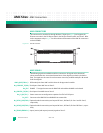
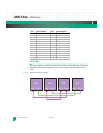
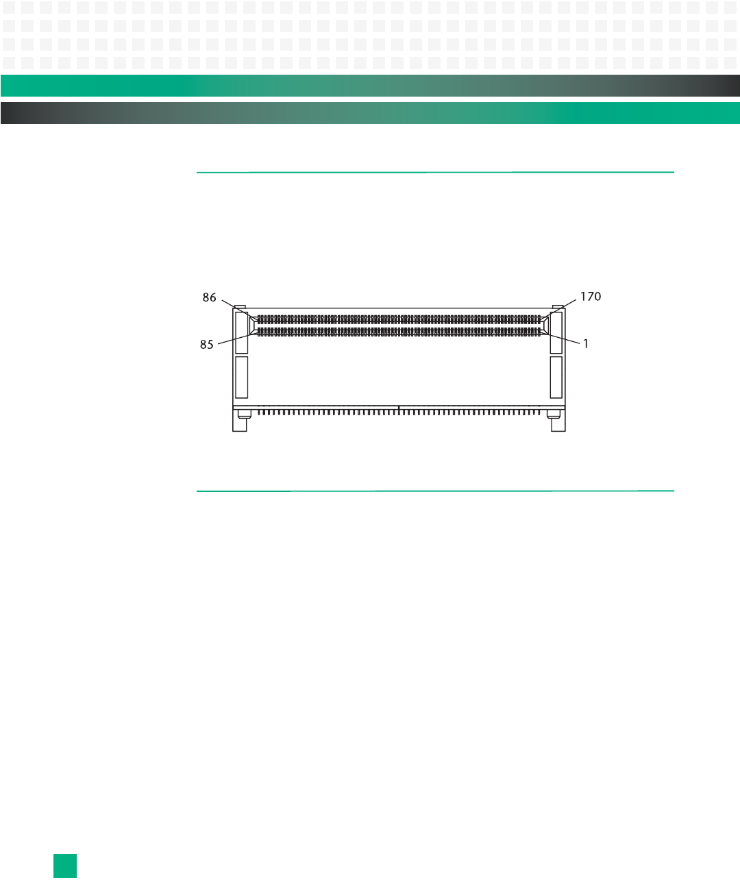
The connectors for modules B1 through B4 have 170 pins (see Fig. 8-1) and support the
Ethernet core switch, the PCI Express Switch, the Fat Pipe Switch module, and Zone 3. Refer
to the component map in
Fig.2-1 for the location and orientation of the AMC B+ connectors
on the KAT4000.
Figure 8-1: AMC B+ Connector
AMC SIGNALS
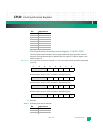
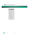
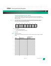
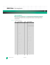
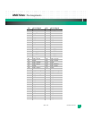
The following signals are available on all four connectors. All signals are bi-directional
unless stated otherwise. A sustained tristate line is driven high for one clock cycle before
float. The signals are the same for each connector since they are differential pairs. Bn stands
for B1 through B4.
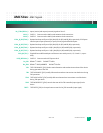
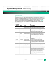
AMCn_RXD/TXDn+/-: Differential pairs from AMC cards B1-B4 to the fat pipe switch module.
Bn_CONSOLE_TX/RX+/-:Serial ports from AMC sites to Zone 3.
Bn_EN*: ENABLE This signal connects to the IPMC PLD and enables the MMC on the board.
Bn_LEDCTRL_TX/RX+/-:Serial ports from AMC sites to Zone 3.
Bn_P1_RX/TX+/-: Power connectors to configuration capacitors for GbE or PCI Express.
Bn_PS1*: Connects to the IPMC PLD via a BMR H8S microcontroller.
Bn_SATA1_RXD/TXD+/-:Optional module connectivity test loop to B3 Sata 1, B4 Sata 2, B1 Sata 1 and B1 Sata 2,
respectively.
Bn_SATA2_RXD/TXD+/-:Optional module connectivity test loop to B4 Sata 1, B3 Sata 2, B2 Sata 2 B2 Sata 1, respec-
tively.
Bn_TRINGn/RRINGn+/-: Input (receive) and output (transmit) signals to Zone 3.


