CPLD: Clock Synchronizer Registers
KAT4000 User’s Manual 10007175-02
7-18
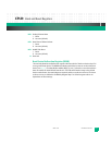
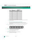
Note: This 8 KHz source is generated by the PLD based off Sync 1 clocks. Therefore, the Sync 1 part must be enabled
for this clock to be active.
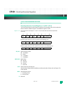
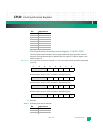
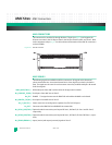
Clock Synchronizer Interrupt Registers (CSI1-CSI3)
The Clock Synchronizer Interrupt registers control the clock synchronizer interrupts.
Default is 0xc0 for all three registers. Default register values are shown in the bottom row of
the register table.
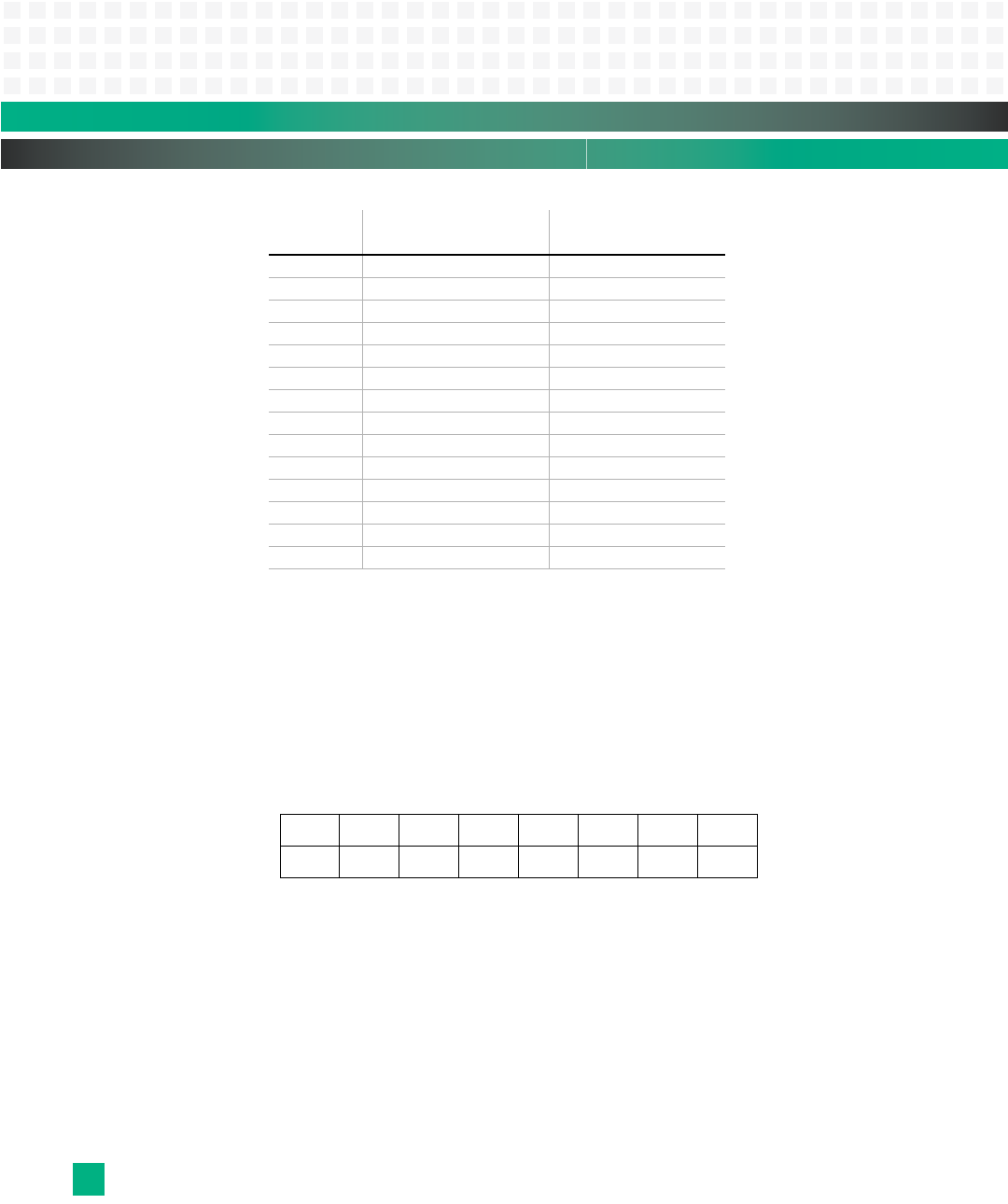
Register 7-20: Clock Synchronizer Interrupt Registers 1-3 (CSI1-CSI3) at 0xfc40,00a8, 0xfc40,00ac, 0xfc40,00b0, respectively
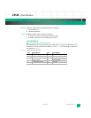
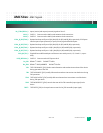
HM, PM: Holdover and PLL Lock Loss Interrupt Masks (read/write)
1 Masks interrupt from being generated to CPU
0 Allows interrupt to be generated to CPU
Note: Bits (3:2) are not affected by bits (7:6).
HIC, PIC: Holdover and PLL Lock Loss Interrupt Clear (write-only)
Setting (1) the bit clears interrupts.
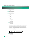
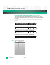
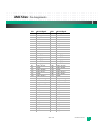
10001 aTCA CLK3 B 14
10010 Sync #1 - 19.44 MHz —
10011 Sync #1 - 2.048 MHz —
10100 Sync #1 - 1.544 MHz —
10101 8 KHz (see note) —
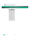
10110 Sync #2 - 19.44 MHz —
10111 Sync #2 - 2.048 MHz —
11000 Sync #2 - 1.544 MHz —
11001 Sync #3 - 19.44 MHz —
11010 Sync #3 - 2.048 MHz —
11011 Sync #3 - 1.544 MHz —
11100 reserved —
... —
11111 reserved —
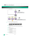
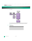
76543210
HM PM HIC PIC HPI PPI HS PS
11000000
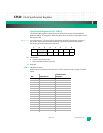
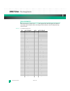
Bit: Input Source:
Clock Control
Register:


