


10007175-02 KAT4000 User’s Manual
7-1
Section 7
CPLD
In addition to reset and interrupt registers, the complex programmable logic device (CPLD)
provides the peripheral bus interface for: user LEDs, configuration jumpers, board revision,
boot device selection, and the hardware configuration register. The CPLD is in-system pro-
grammable (ISP). A single JTAG interface is provided for local programming. Remote pro-
gramming via the IPMC is also possible.
All reset sources and loads are connected to the CPLD. The board can be remotely reset via
the IPMI controller. Software can also assert a board-level reset.
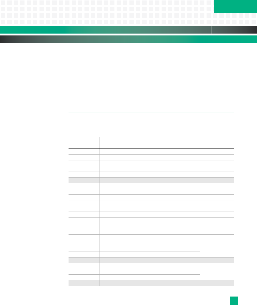
PLD REGISTER SUMMARY
The PLD registers start at address FC40,0000
16
. Tab le 7 -1 lists the 8-bit PLD registers fol-
lowed by the register bit descriptions.
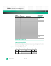
Table 7-1: PLD Registers
Address
Offset (hex): Mnemonic: Register Name: Register Map:
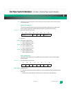
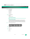
0x00 PIDR Product ID 7-1
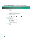
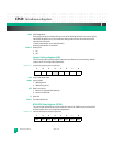
0x04 HVR Hardware Version 7-2
0x08 PVR PLD Version 7-3
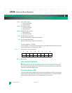
0x0C PLLC PLL Configuration 7-5
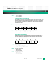
0x10 HCR0 Hardware Configuration 0 7-4
0x14 — Reserved —
0x18 JSR Jumper Settings 7-7
0x1C LEDR LED Control 7-6
0x20 RER Reset Event 7-12
0x24 RCR1 Reset Command 1 7-13
0x28 RCR2 Reset Command 2 7-14
0x2C SCR1 Scratch 1 7-11
0x30 BDRR Boot Device Redirection 7-15
0x34 MISC MISC Control 7-10
0x38 RGSR RTM GPIO State 7-8
0x3C RGCR RTM GPIO Control 7-9
0x40 CSC1 Clock Synchronizer Control 1
7-160x44 CSC2 Clock Synchronizer Control 2
0x48 CSC3 Clock Synchronizer Control 3
0x4C — Reserved —
0x50 CPS1 Clock Synchronizer Primary Source 1
7-170x54 CPS2 Clock Synchronizer Primary Source 2
0x58 CPS3 Clock Synchronizer Primary Source 3
0x5C — Reserved —