


Real-Time Clock: Clock Operation
10007175-02 KAT4000 User’s Manual
11-3
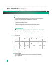
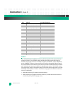
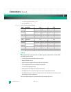
Day: Day of the week
Date: Day of the month
OUT: Output level
1 Default at initial power-up
0 FT/OUT (pin 7) driven low when FT is also zero
FT: Frequency Test bit
1 When oscillator is running at 32,768 Hz, the FT/OUT pin will toggle at 512 Hz
0 The FT/OUT pin is an output driver (default at initial power-up)
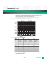
S: Sign bit
1 Positive calibration
0 Negative calibration
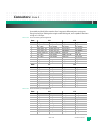
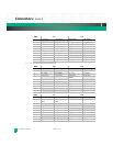
Calibration: Calibration bits The calibration circuit adds or subtracts counts from the oscillator divider
circuit at the divide by 256 stage. The number of times pulses are blanked (subtracted, neg-
ative calibration) or split (added, positive calibration) depends on this five-bit byte. Adding
counts accelerates the clock, and subtracting counts slows the clock down.
X: Don’t care bit