Setup: KAT4000 Circuit Board
10007175-02 KAT4000 User’s Manual
2-7
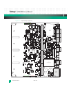
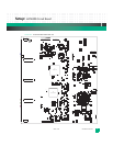
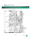
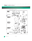
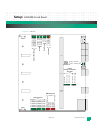
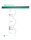
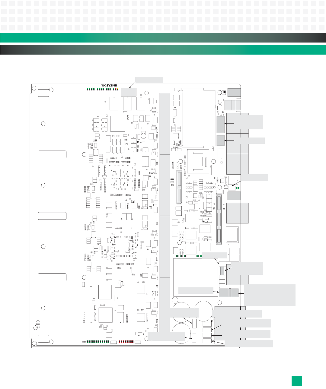
Figure 2-4: Jumper, Fuse and Switch Locations, Top
JP3 - PLD Prog. JTAG
JP4 - Serial Port:
1-4 IPMC
7-10 Fat Pipe Module
13-16 Host CPU
SW2 - Main Reset
JP7 - Boot
1:2 Boot from socket (defaultinstalled)
3:4 Ignore SROM
5:6 Enable boot redirection
7:8 Logic probe
9:10 Standalone (SA) mode
JP2 - IPMC
1:2 IPMC Mode bit MD2
3:4 IPMC Mode bit MD1
SW1 - IPMC Reset
JP1 - PLD Config. Header
F3 - Fuse
F5 - Fuse
F6 - Fuse
F4 - Fuse
F2 - Fuse
F1 - Fuse
P1 - CPU JTAG/COP


