


Connectors: Zone 3
KAT4000 User’s Manual 10007175-02
12-4
• m is the logical slot number (1-16)
•p is the polarity (+, -)
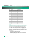
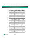
Table 12-3: Zone 2 Connector, J23 Pin Assignments
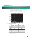
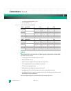
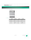
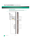
ZONE 3
These optional Zone 3 type A connectors, J30 through J33, support a Rear Transition Mod-
ule (RTM). Features include:
• Two SerDes ports from the Ethernet core switch
• Routing all AMC user I/O
• Power routed to support active logic with hot swap control
•I
2
C bus from IPMC for system management purposes
•I
2
C bus from payload processor
• Payload processor debug Ethernet port connection
• KAT4000 with CPU: Console serial port interfaces for the payload processor
• KAT4000 without CPU: Console serial port interfaces for the Ethernet core switch and fat
pipe Ethernet switch console ports
Connectors J30 through J32 use the same ZD-style connector as Zone 2.
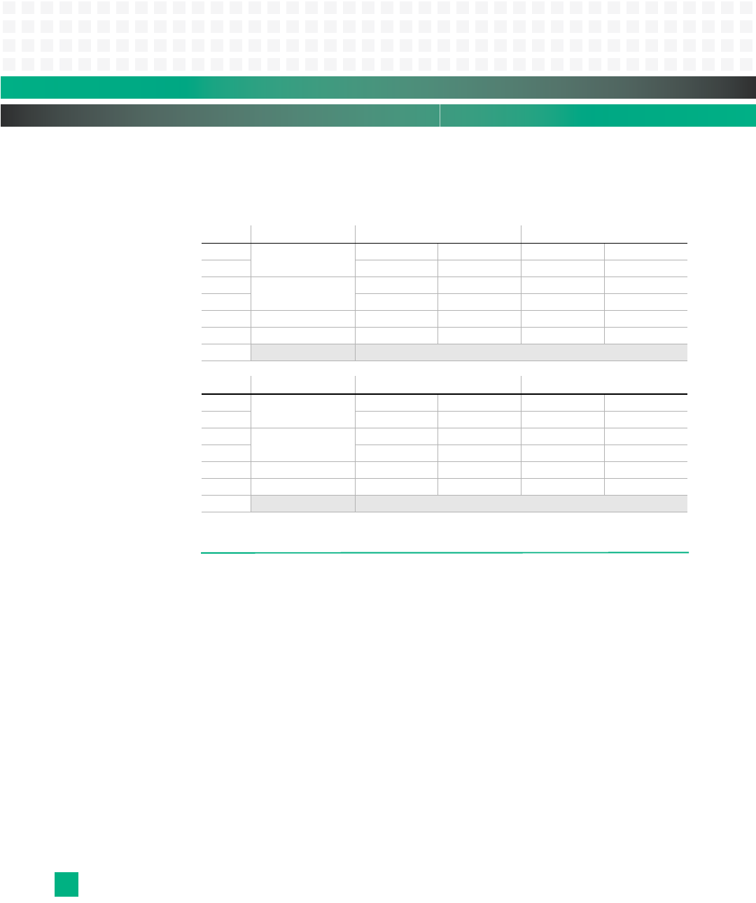
Row: Interface: A B C D
1 Fabric Channel 2 Tx2[2]+ Tx2[2]- Rx2[2]+ Rx2[2]-
2 Tx0[2]+ Tx0[2]- Rx0[2]+ Rx0[2]-
3 Fabric Channel 1 Tx2[1]+ Tx2[1]- Rx2[1]+ Rx2[1]-
4 Tx0[1]+ Tx0[1]- Rx0[1]+ Rx0[1]-
5 Base Ethernet 1 XBC1_TR0+ XBC1_TR0- XBC1_TR1+ XBC1_TR1-
6 Base Ethernet 2 XBC2_TR0+ XBC2_TR0- XBC2_TR1+ XBC2_TR1-
7-10
na no connect
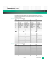
Row: Interface: E F G H
1 Fabric Channel 2 Tx3[2]+ Tx3[2]- Rx3[2]+ Rx3[2]-
2 Tx1[2]+ Tx1[2]- Rx1[2]+ Rx1[2]-
3 Fabric Channel 1 Tx3[1]+ Tx3[1]- Rx3[1]+ Rx3[1]-
4 Tx1[1]+ Tx1[1]- Rx1[1]+ Rx1[1]-
5 Base Ethernet 1 XBC1_TR2+ XBC1_TR2- XBC1_TR3+ XBC1_TR3-
6 Base Ethernet 2 XBC2_TR2+ XBC2_TR2- XBC2_TR3+ XBC2_TR3-
7-10
na no connect