Fat Pipe Switch Module: GbE Fat Pipe Switch Module
10007175-02 KAT4000 User’s Manual
5-9
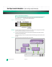
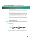
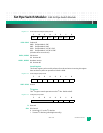
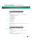
Register 5-6: Module Status Register (STAT) at 0x05
R: Reserved
CPU: Switch Mode
0 Internal 8051 microcontoller disabled, parallel interface used for management access
1 Internal 8051 microcontroller enabled
S2V5: 2.5V Power Supply Status
0 Power supply out of spec
1 Power supply within spec
S1V2: 1.2V Power Supply Status
0 Power supply out of spec
1 Power supply within spec
INT1, INT0: Switch Interrupts
0 No interrupt pending
1 Interrupt pending
Switch GPIO Register
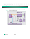
The Switch GPIO register drives the GPIO signals on the VSC7376 Ethernet switch. Default is
0x00.
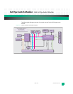
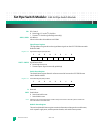
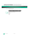
Register 5-7: Switch GPIO Register (GPIO) at 0x06
GPIO7–GPIO0: GPIO State
0Drive logic low
1 Drive logic high
Note: When the internal 8051 microcontroller is enabled, GPIOs 5:4 are disabled, as they are used for other func-
tions. The PLD will tristate these pins.
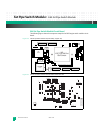
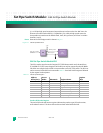
GPIN/LED Register
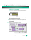
The GPIN/LED register controls general purpose inputs to the PLD from the carrier. There
are also four LEDs which are under software control.
76543210
reserved CPU S2V5 S1V2 INT1 INT0
76543210
GPIO7 GPIO6 GPIO5 GPIO4 GPIO3 GPIO2 GPIO1 GPIO0


