Rear Transition Module: Installation
10007175-02 KAT4000 User’s Manual
13-7
❐ Card cage and power supply
❐ Computer terminal
When you unpack the module, save the antistatic bag and box for future shipping or stor-
age.
Identification Numbers
Before you install the KAT-Z3DB in a system, you should record the following information:
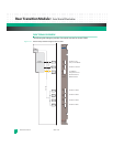
• The board serial number: 711G- _____________________________________ .
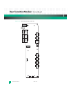
The board serial number appears on a bar code sticker located at the top of the board
near A1 (see
Fig. 13-2).
• The board product identification (ID): ________________________________ .
This product ID sticker is located in the middle of the board across from P5 and P6 (see
Fig. 13-2).
It is useful to have these numbers available when you contact Technical Support at Emer-
son.
INSTALLATION
Caution: To avoid damaging the module and/or baseboard, do not force the module onto the
baseboard.
Caution: Use proper static protection and handle KAT4000 boards only when absolutely necessary.
Always wear a wriststrap to ground your body before touching a board. Keep your body
grounded while handling the board. Hold the board by its edges–do not touch any
components or circuits. When the board is not in an enclosure, store it in a static-shielding
bag.
When installing a KAT-Z3DB to the backplane, follow these guidelines:
1 To prevent ESD damage to the KAT4000, wear a grounding wrist strap and use a grounded
work surface while handling the board.
Note: The ESD strip on the bottom edge of the RTM provides a controlled discharge path before the Zone 3 connec-
tors engage.
2 The KAT-Z3DB receives all its power from the front board. To install or remove the KAT-
Z3DB, either Hot Swap the KAT4000 or install the KAT-Z3DB with the KAT4000’s Hot Swap
switch open (no power).
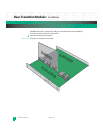
3 First align the RTM Zone 3 connectors (P30-P33) to the KAT4000 connectors (J30-J33).
Then align both two-pin ATCA guides: the RTM’s A1 (Zone 3) and K1 (Zone 2) to the
!
!


