10007175-02 KAT4000 User’s Manual
4-1
Section 4
Common Switch Region
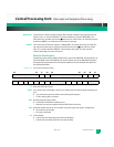
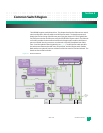
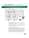
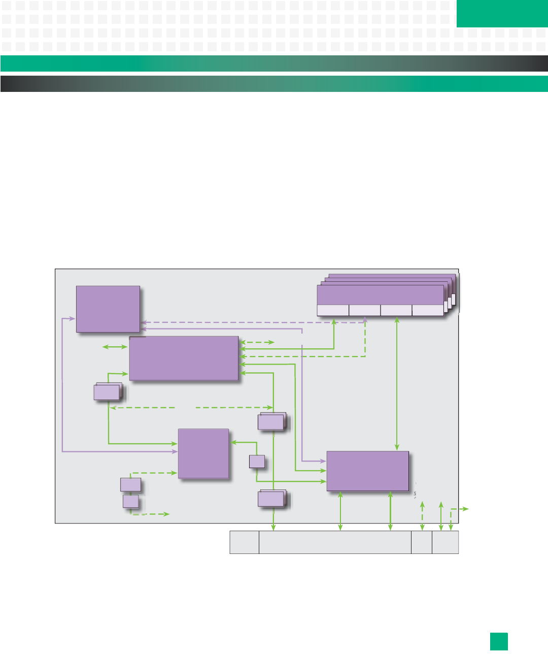
The KAT4000 supports multiple interfaces. This chapter describes the Ethernet core switch,
switch configuration, Ethernet address and PCI Express switch. The board area network
(BAN) refers to the routing of the Ethernet ports using the Vitesse VSC7376 Gigabit Ether-
net (GbE) core switch or the PCIe ports using the PEX 8524 PCI Express switch. The Ethernet
core switch provides the interconnect between the fat pipe switch module, the Ethernet
ports on the AMC sites, the processor, two channels on the ATCA backplane base fabric,
Zone 3, and the Update Channel (optional) (see
Fig. 4-1). The PCI Express switch provides
the interconnect between the AMC sites, the processor, and the fat pipe switch module.
Both switches are optional, however at least one of the two must be used on the board. The
board can also use both switches.
Figure 4-1: Board Area Network
VSC7376
Ethernet Core
Switch
Layer 2
(Optional)
MPC8548
Processor
(Optional)
IPMB Base High Speed
Fabric A
Clock RTM I/O
(Optional)
High Speed
Fabric B
10/100 Debug Eth (MII)
To Zone 3
(Optional)
Zone 3
Connections
(Opt.)
To
Core
Eth
Switch
(Opt.)
SERDES
RGMII
Xfmr
Xfmr (2)
GbE
PHYs (2)
4
GMII/RGMII
10/100
PHY
Xfmr
GbE Fat Pipe
Switch Module
(Optional)
GbE
PHY
2
AMC (x4) Single Wide,
Mid-Size or Compact
To
Core
Eth
Switch
2
To Zone 3
2 SERDES
SERDES
4 SERDES
4 SERDES
4 SERDES
2 SGMII
SERDES
SERDES
4 SERDES
SERDES
GbE
PHYs (2)
Optional
PCIe or GbE
on port 1
PCIe
(x1 or x4)
PEX8524
PCI Express Switch
(Optional)
PCIe
To Update Channel
on J20 (Optional)
710
11
15,17
4,6
14,16
0,2:B1 12,13:B2
18,20:B3 22,24:B4
811:B3
12
13
47 03
1417:B4
1821:B2
2225:B1
0
1
8:B1
10:B3
9:B2
11:B4
PCIe
GbE
GbE
GbE
GbE
GbE
P10 J20 Zone 3J23


