Common Switch Region: PCI Express Switch (optional)
10007175-02 KAT4000 User’s Manual
4-9
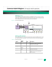
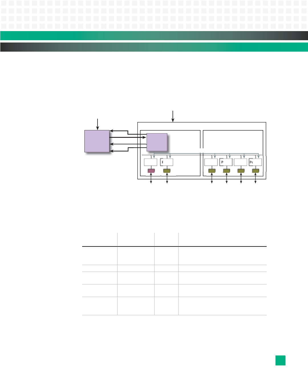
EEPROM Interface
The PEX 8524 has an embedded 64-kilobyte SPI EEPROM controller. This direct interface
provides the 7.8 MHz serial clock (EE_SK), chip select (EE_CS*), and data output (EE_DO)
for the EEPROM; and receives data input (EE_DI) from the EEPROM.
Figure 4-4: PEX 8524 SPI EEPROM Interface
JTAG Controller Interface
The PEX 8524 supports a five pin JTAG interface that complies with IEEE standard 1149.1
and 1149.6 Boundary-Scan signals. The JTAG interface consists of the following signals:
Table 4-5: PEX 8524 JTAG Signals
Signal:
Signal
Name: Type: Description:
JTAG_ TCK Test clock in This is the clock source for the PEX 8524
Test Access Port (TAP) and may be any
frequency from 0 to 10 MHz.
JTAG_ TDI Test data input in This inputs data to the TAP.
JTAG_ TDO Test data
output
out This transmits serial data from the TAP.
JTAG_ TMS Test mode
select
in The TAP state machine uses the TMS to
determine the TAP mode.
JTAG_ TRST* Test reset in This resets JTAG and the TAP. It should be
toggled or held at 0 for the PEX 8524 to
function properly.
PEX 8524
Initialization
Serial
EEPROM
EE_CS*
EE_DI
EE_DO
EE_SK
+3.3 V
+3.3 V
Serial
EEPROM
Controller
Port 1Port 0 Port 9Port 8 Port 11Port 10
Configuration Data


