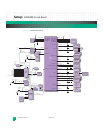
Central Processing Unit: Microprocessor Core (e500)
KAT4000 User’s Manual 10007175-02
3-4
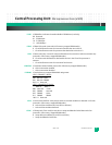
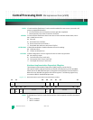
4 Poll L2CR[L2I] until it is cleared.
5 Enable the L2 cache for normal operation and then set the L2CR[L2E].
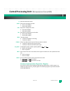
Timer/Counter
Each of the four 32-bit wide timer/counters can be selected to operate as a timer or a
counter. Each timer/counter increments with every TCLK rising edge. In counter mode, the
counter counts down to terminal count, stops, and issues an interrupt. In timer mode, the
timer counts down, issues an interrupt on terminal count, reloads itself to the programmed
value, and continues to count. Reads from the counter or timer are completed directly from
the counter, and writes are to the timer/counter register.
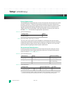
PCI Device and Vendor ID Assignment
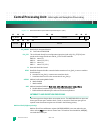
The KAT4000 has been assigned the following PCI identification number:
Table 3-2: PCI Device and Vendor ID
The KAT4000 sets the PCI revision ID to the hardware version number located in the CPLD’s
Hardware Version register (Register Map 7-2).
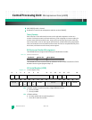
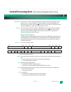
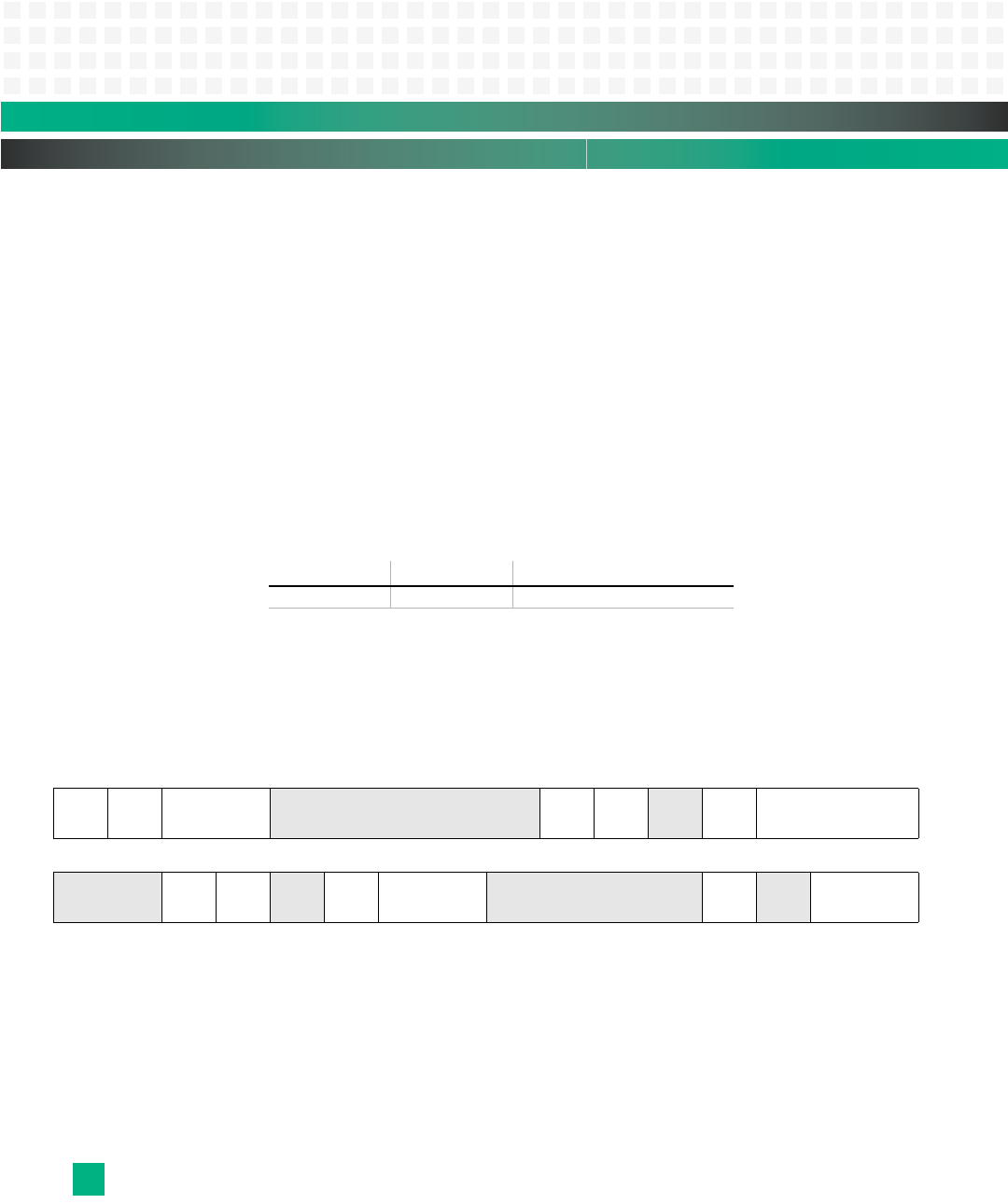
L2 Control Register (L2CR)
Register 3-1: L2 Control Register (L2CR)
L2E: L2 Enable—enables L2 cache or memory-mapped SRAM (L2 array).
0 L2 array disabled
1 L2 array enabled
L2I: L2 Flash Invalidate
0 L2 status and LRU bits are not being cleared
1 Clears all L2 status bits and LRU
Vendor ID: Device ID: Description:
0x1223 0x001B Reported by the PCI bridge
0123456 8910111213 15
L2E L2I L2SIZ reserved L2
DO
L2I0 RL2IN
TDIS
L2SRAM
16 17 18 19 20 21 22 23 24 27 28 29 30 31
reserved L2
LO
L2
SLC
RL2LF
R
L2LFRID reserved
L2STA
SHDIS
RL2STASH


