Monitor: Basic Operation
10007175-02 KAT4000 User’s Manual
14-5
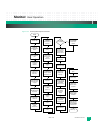
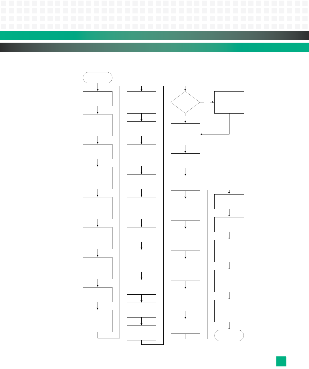
Figure 14-3: Power-up/Reset Sequence Flowchart
RESET
Initialize HID0
Initialize MSR
Relocate the
MPC8548
CCSRBDR base
address
Map LAWBARs/
TLBs
Invalidate the
L2 cache
LED 0001
Invalidate and
enable the L1
data cache
Setup initial stack
and data region
in cache
Configure the
MPC8548 device
chip selects
Enable icache
LED 0010
Initialize the
U-Boot
environment
Init. serial port per
baudrate
environment var.
LED 0011
Display version
string
Display CPU,
board, and bus
speed
LED 0100
Initialize
I
2
C
Init. SDRAM. Clear
per clearmem and
configure per ecc
environment vars.
Initialize
final stack
Relocate U-Boot
to RAM
LED 0110
Initialize
flash
Initialize malloc
area
Initialize
PCIe
Is module a
root complex
Enumerate PCI
per enumerate
environment
variable
Yes
Display board
serial number
No
Configure dcache
per cachemode
and dcache
environment vars.
Configure icache
per icache
environment
variable
Configure L2
cache per l2cache
and l2mode
environment vars.
Initialize Ethernet
ports
Turn off debug
LEDs and blink
front panel red
LED per blinked
environment var.
Main Loop
Initialize
disk-on-chip
Perform board
diagnostics per
powerondiags
environment var.
Enable MPC8548
external interrupts
Relocate IRQ
handlers and
IRQ traps
Display LED 0111
Initialize fat pipe
Ethernet switch,
if installed
Initialize core
Ethernet switch,
if installed


