CPLD: Clock Synchronizer Registers
10007175-02 KAT4000 User’s Manual
7-17
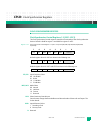
Clock Control Registers (CCR1—CCR14)
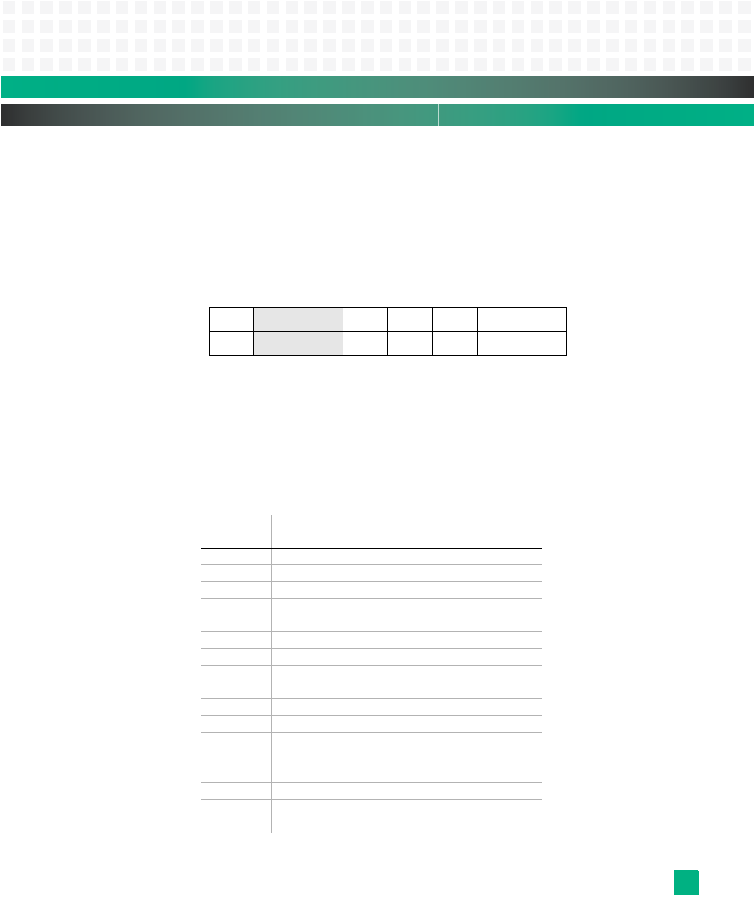
The Clock Control registers control the source clock to the various clock destinations.
Default is 0x0E for all 14 registers. Default register values are shown in the bottom row of
the register table.
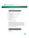
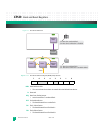
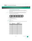
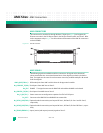
Register 7-19: Clock Control Registers 1-14 (CCR1-CCR14) at 0xfc40,0070, 0xfc40,0074, 0xfc40,0078, 0xfc40,007c,
0xfc40,0080, 0xfc40,0084, 0xfc40,0088, 0xfc40,008c, 0xfc40,0090, 0xfc40,0094, 0xfc40,0098,
0xfc40,009c, 0xfc40,00a0, 0xfc40,00a4, respectively
OE: Clock Enable
0 Tristates clock driven to site
1 Drives selected clock source to site
R: Reserved
CSS4-0: Clock Source Select
Defines source of clock to be driven to site. If “self” is selected as source, logic “0” will be
driven.
76543210
OE reserved CSS4 CSS3 CSS2 CSS1 CSS0
0
01110
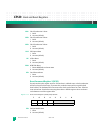
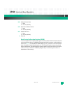
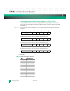
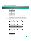
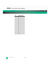
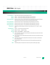
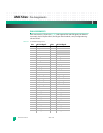
Bit: Input Source:
Clock Control
Register:
00000 AMC1 CLK1 1
00001 AMC1 CLK2 2
00010 AMC1 CLK3 3
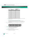
00011 AMC2 CLK1 4
00100 AMC2 CLK2 5
00101 AMC2 CLK3 6
00110 AMC3 CLK1 7
00111 AMC3 CLK2 8
01000 AMC3 CLK3 9
01001 AMC4 CLK1 10
01010 AMC4 CLK2 11
01011 AMC4 CLK3 12
01100 aTCA CLK1 A —
01101 aTCA CLK1 B —
01110 aTCA CLK2 A —
01111 aTCA CLK2 B —
10000 aTCA CLK3 A 13


