Fat Pipe Switch Module: GbE Fat Pipe Switch Module
KAT4000 User’s Manual 10007175-02
5-6
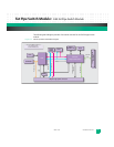
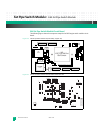
J1 is a 120-pin high-speed connector that provides an interface to the four AMC sites, the
Ethernet core switch and an 88E1111 Gigabit PHY. J2 is a 180-pin high-speed connector
that provides an interface to the RTM channel, clock, PLD, processor, and Zone 2 via fabric
channels 1 and 2.
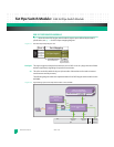
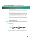
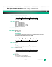
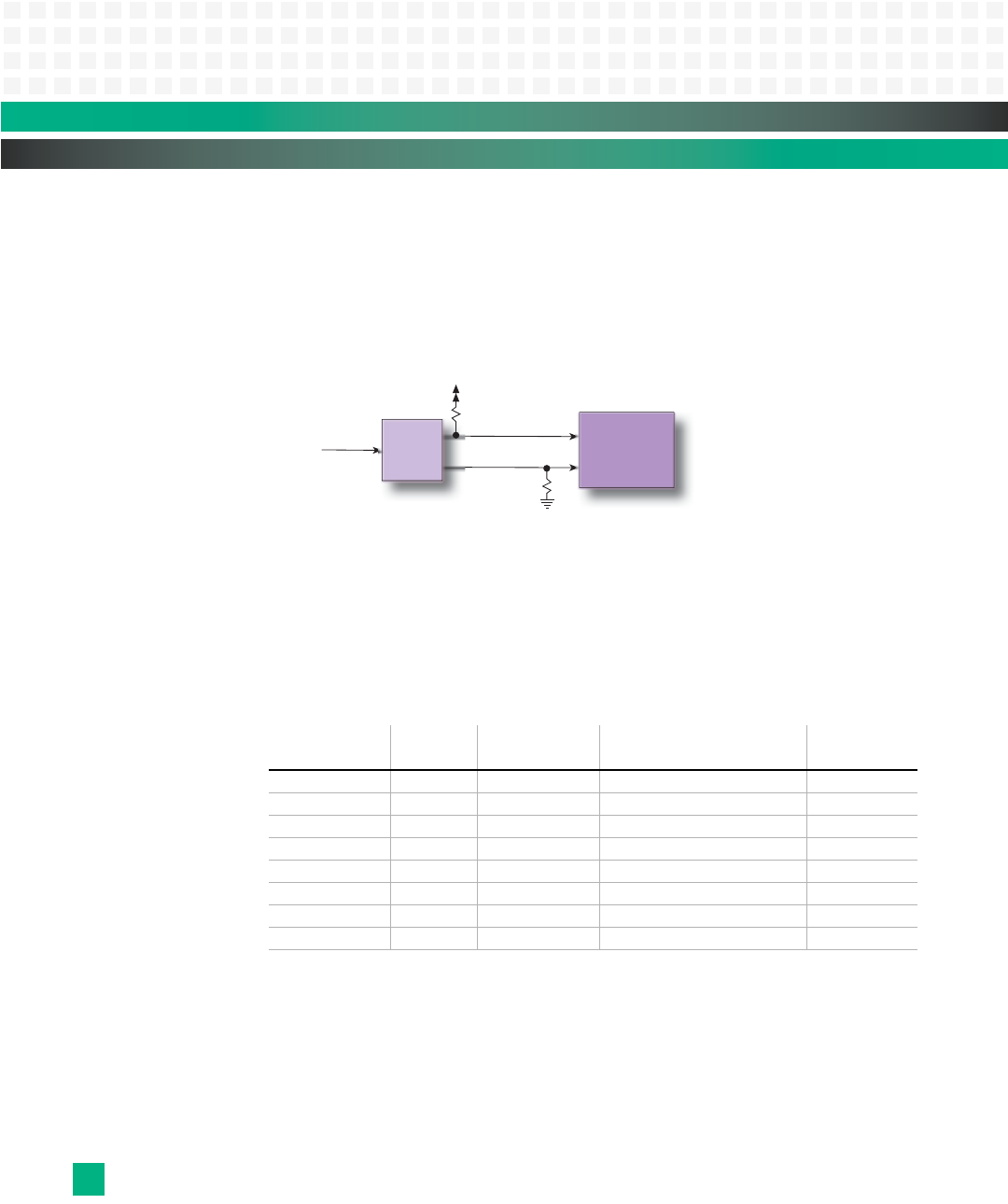
Reset: Reset of the GbE fat pipe switch is shown in
Fig. 5-7.
Figure 5-7: GbE Fat Pipe Switch Reset
GbE Fat Pipe Switch Module PLD
The PLD is used to interface to the fat pipe VSC7376 Ethernet switch and is located from
FC14,0000-FC15,FFFF. Internal registers of the PLD can only be accessed by the KAT4000’s
CPU when not using the built-in 8051 microcontroller on the VSC7376 switch. The PLD can-
not be accessed via the 8051 microcontroller.
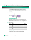
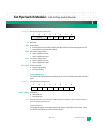
Table 5-1 lists the 8-bit PLD registers followed
by the register bit descriptions.
Table 5-1: GbE Fat Pipe PLD Registers
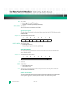
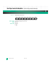
Product ID/Version Register
The read-only Product ID/Version register indicates the product type, PLD code version,
and hardware version. The values of these bits are hard-coded inside the PLD.
Address
Offset (hex):
Access
Mode: Mnemonic: Register Name:
Register
Map:
0x00 R PIDV Product ID/Version Register 5-1
0x01 R/W SCR Scratch Register 5-2
0x02 R/W I
2
CI
2
C Register 5-3
0x03 R/W SDET Signal Detect Register 5-4
0x04 R/W SRST Switch Reset Register 5-5
0x05 R STAT Module Status Register 5-6
0x06 R/W GPIO Switch GPIO Register 5-7
0x07 R/W GPLED GPIN/LED Register 5-8
SWITCH_RST*
SWITCH_TRST*
RESET*
PLD
VSC7376
GbE
Switch
3_3V


