Fat Pipe Switch Module: GbE Fat Pipe Switch Module
KAT4000 User’s Manual 10007175-02
5-8
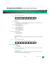
SCL: SCL Control
0Drives logic “0” on the I
2
C clock line
1Tristates I
2
C clock line (pulled high externally)
ADD1, ADD0: I
2
C Address
Values in these bits drive address to I
2
C ROM
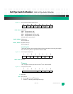
Signal Detect Register
The Signal Detect register drives the signal detect signals on the VSC7376 Ethernet switch.
Default is 0x00.
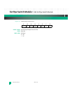
Register 5-4: Signal Detect Register (SDET) at 0x03
SDET7–SDET0: Signal Detect State
0 Drives logic low on net
1 Tristate output. Signal is externally pulled high
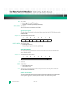
Switch Reset Register
The Switch Reset register allows for software control of reset to the VSC7376 Ethernet
switch. Default is 0x00.
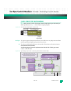
Register 5-5: Switch Reset Register (SRST) at 0x04
R: Reserved
SRST: Switch Reset
0 Switch not held in reset
1 Switch held in reset
Note: Software must ensure that the switch is held in reset for the minimum amount of time as listed in the
VSC7376 Ethernet switch data sheet.
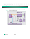
Module Status Register
The read-only Module Status register contains information relating to the module status,
such as power supply state, switch operational mode, and switch interrupt state.
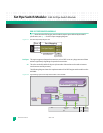
76543210
SDET7 SDET6 SDET5 SDET4 SDET3 SDET2 SDET1 SDET0
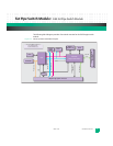
76543210
reserved SRST


