


Epson Research and Development
Page 107
Vancouver Design Center
Hardware Functional Specification S1D13505
Issue Date: 01/02/02 X23A-A-001-14
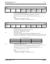
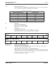
bits 4-2 Bit-per-pixel Select Bits [2:0]
These bits select the color depth (bpp) for the displayed data. See
“Section 10.1 Display Mode For-
mats”
for details of how the pixels are mapped into the image buffer.
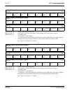
bit 1 CRT Enable
This bit enables the CRT monitor.
When this bit = 1, the CRT is enabled.
When this bit = 0, the CRT is disabled.
bit 0 LCD Enable
This bit enables the LCD panel.
Programming this bit from a 0 to a 1 starts the LCD power-on sequence.
Programming this bit from a 1 to a 0 starts the LCD power-off sequence.
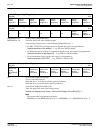
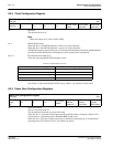
REG[0Eh] bits 7-0 Screen 1 Line Compare Bits [9:0]
REG[0Fh] bits 1-0 These bits are set to 1 during power-on.
The display can be split into two images: Screen 1 and Screen 2, with Screen 1 above Screen 2.
This 10-bit value specifies the height of Screen 1.
Height of Screen 1 (lines) = Screen 1 Line Compare Bits [9:0] + 1
If the height of Screen 1 is less than the display height then the remainder of the display is taken up
by Screen 2. For normal operation (no split screen) this register must be set greater than the Vertical
Display Height register (e.g. set to the reset value of 3FFh).
See “
Display Configuration”
for details.
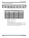
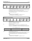
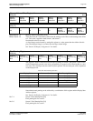
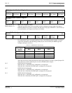
Table 8-7: Bit-per-pixel Selection
Bit-per-pixel Select Bits [2:0] Color Depth (bpp)
000 1 bpp
001 2 bpp
010 4 bpp
011 8 bpp
100 15 bpp
101 16 bpp
110
–
111 Reserved
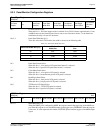
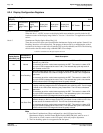
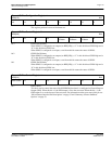
Screen 1 Line Compare Register 0
REG[0Eh] RW
Screen 1 Line
Compare Bit 7
Screen 1 Line
Compare Bit 6
Screen 1 Line
Compare Bit 5
Screen 1 Line
Compare Bit 4
Screen 1 Line
Compare Bit 3
Screen 1 Line
Compare Bit 2
Screen 1 Line
Compare Bit 1
Screen 1 Line
Compare Bit 0
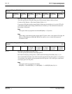
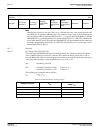
Screen 1 Line Compare Register 1
REG[0Fh] RW
n/an/an/an/an/an/a
Screen 1 Line
Compare Bit 9
Screen 1 Line
Compare Bit 8