


Epson Research and Development
Page 113
Vancouver Design Center
Hardware Functional Specification S1D13505
Issue Date: 01/02/02 X23A-A-001-14
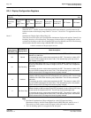
This register position is reserved for future use.
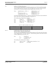
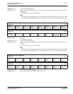
bit 3 GPIO3 Pin IO Status
When GPIO3 is configured as an output (see REG[1Eh]), a “1” in this bit drives GPIO3 high and a
“0” in this bit drives GPIO3 low.
When GPIO3 is configured as an input, a read from this bit returns the status of GPIO3.
bit 2 GPIO2 Pin IO Status
When GPIO2 is configured as an output (see REG[1Eh]), a “1” in this bit drives GPIO2 high and a
“0” in this bit drives GPIO2 low.
When GPIO2 is configured as an input, a read from this bit returns the status of GPIO2.
bit 1 GPIO1 Pin IO Status
When GPIO1 is configured as an output (see REG[1Eh]), a “1” in this bit drives GPIO1 high and a
“0” in this bit drives GPIO1 low.
When GPIO1 is configured as an input, a read from this bit returns the status of GPIO1.
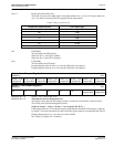
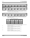
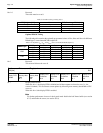
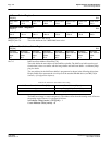
bit 7 GPO Control
This bit is used to control the state of the SUSPEND# pin when it is configured as General Purpose
Output (GPO). When this bit = 0, the GPO output is set to the reset state. When this bit = 1, the
GPO output is set to the inverse of the reset state. For information on the reset state of this pin see
“Miscellaneous Interface Pin Descriptions“ on page 32 and “Summary of Power On/Reset
Options“ on page 33.
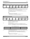
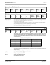
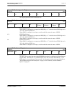
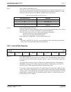
General IO Pins Configuration Register 1
REG[1Fh] RW
n/a n/a n/a n/a n/a n/a n/a n/a
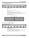
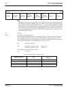
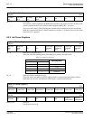
General IO Pins Control Register 0
REG[20h] RW
n/a n/a n/a n/a
GPIO3 Pin
IO Status
GPIO2 Pin
IO Status
GPIO1 Pin
IO Status
n/a
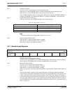
General IO Pins Control Register 1
REG[21h] RW
GPO Control n/a n/a n/a n/a n/a n/a n/a