


Page 14
Epson Research and Development
Vancouver Design Center
S1D13505 Interfacing to the NEC V832™ Microprocessor
X23A-G-012-02 Issue Date: 01/02/05
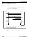
4.3 NEC V832
Configuration
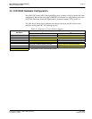
The NEC V832 should access the S1D13505 in non-burst mode only. This is ensured by
using any one of the CS3
to CS6 lines to control the S1D13505 and setting that line to
respond to IO operations using the NEC V832 BCTC register. For example, if line CS5
is
designated to control the S1D13505, then bit 5 (CT5) of the BCTC register should be set to
1 (IO cycle).
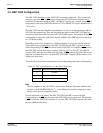
The NEC V832 data bus should be programmed to use 16 bits as the maximum width for
S1D13505 bus transactions. This does not affect the width of other NEC V832 data bus
transactions. Data bus width is set in the NEC V832 DBC register. For example, if line CS4
is designated to control the S1D13505, then bit 4 (BW4) of the DBC register should be set
to 1 (16-bit bus width).
Depending on bus clock frequencies, a different number of wait states may be required.
These need to be programmed into the NEC V832 PWC0 and PWC1 registers in the bit
field corresponding to the CSn
line chosen for the S1D13505. For example, if CS3 controls
the S1D13505 and one wait state is required, then bits 14-12 of the NEC V832 PWC0
register (WS3) must be set to 001b (one wait state). If CS6
controls the S1D13505 and no
wait state is needed, then bits 11-8 of the NEC V832 PWC1 register (WS6) must be set to
0000b (zero wait state).
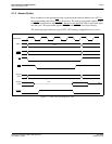
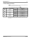
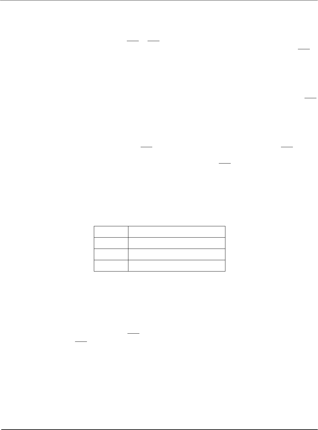
The table below shows the recommended wait states depending on the bus clock frequency.
Note
The host interface of the S1D13505 is slower when disabled. Therefore, while the host
interface is disabled (REG[1Bh] bit 7 = 1), an additional wait state is required to main-
tain the same respective frequency limits.
No idle state needs to be added. The NEC V832 PIC0 and PIC1 register bit field
corresponding to the CSn
line chosen for the S1D13505 must be set to zero. For example,
if CS3
controls the S1D13505, then bits 14-12 of the NEC V832 PIC0 register (IS3) must
be set to 000b (no idle state).
Table 4-2: NEC
V
832 Wait States vs. Bus Clock Frequency
Wait States Maximum Frequency (SDCLKOUT)
012.5MHz
1 37MHz
2No limit