


Page 20
Epson Research and Development
Vancouver Design Center
S1D13505 Programming Notes and Examples
X23A-G-003-07 Issue Date: 01/02/05
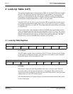
4 Look-Up Table (LUT)
This section is supplemental to the description of the Look-Up Table architecture found in
the S1D13505 Hardware Functional Specification. Covered here is a review of the LUT
registers, recommendations for the color and gray shade LUT values, and additional
programming considerations for the LUT. Refer to the S1D13505 Hardware Functional
Specification, document number X23A-A-001-xx for more detail.
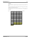
The S1D13505 Look-Up Table is used for both the CRT and panel interface and consists
of 256 indexed red/green/blue entries. Each entry is 4 bits wide. Two registers, at offsets
24h and 26h, control access to the LUT. Color depth affects how many indices will be used
for image display.
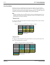
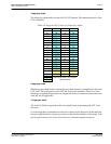
In color modes, pixel values are used as indices to an RGB value stored in the Look-Up
Table. In monochrome modes only the green component of the LUT is used. The value in
the display buffer indexes into the LUT and the amount of green at that index controls the
intensity. Monochrome mode look-ups are done for the panel interface only. The CRT
interface always receives the RGB values from the Look-Up Table.
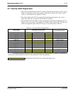
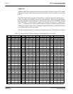
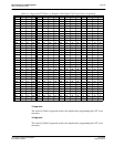
4.1 Look-Up Table Registers
LUT Address
The LUT address register selects which of the 256 LUT entries will be accessed. Writing
to this register will select the red bank. After three successive reads or writes to the data
register this register will be incremented by one.
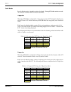
LUT Data
This register is where the 4-bit red/green/blue data value is written or read. With each
successive read or write the internal bank select is incremented. Three reads from this
register will result in reading the red, then the green, and finally the blue values associated
with the index set in the LUT address register.
After the third read the LUT address register is incremented and the internal index points
to the red bank again.
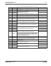
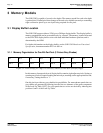
REG[24h] Look-Up Table Address Register Read/Write
LUT Address
Bit 7
LUT Address
Bit 6
LUT Address
Bit 5
LUT Address
Bit 4
LUT Address
Bit 3
LUT Address
Bit 2
LUT Address
Bit 1
LUT Address
Bit 0
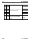
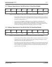
REG[26h] Look-Up Table Data Register Read/Write
LUT Data
Bit 3
LUT Data
Bit 2
LUT Data
Bit 1
LUT Data
Bit 0
n/a n/a n/a n/a