


Epson Research and Development
Page 11
Vancouver Design Center
Evaluation Board User Manual S5U13505-D9000
Issue Date: 01/02/05 X23A-G-002-04
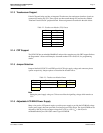
2.1.3 Touchscreen Support
If the LCD panel being used has an integrated Touchscreen, the touchscreen interface signals are
connected to header strip TS1. These signals are then routed through JP3 and into the standard
"Platform II Audio/Touch" peripheral board. Pinout assignment is described in the table below.
2.1.4 CRT Support
The S1D13505 has an embedded RAMDAC and provides complete one-chip CRT support. Refer to
the Programmer’s Notes and Examples, document number X23A-G-003-xx, for programming
details.
2.1.5 Jumper Selection
Jumpers labelled LCDVCC1 and FPS2 provide LCD logic supply voltage and connector pinout
options respectively. Jumper options are described in the table below.
Note
Setting the panel supply voltage to 5V does not affect the signalling voltage which remains at
3.3V.
2.1.6 Adjustable LCD BIAS Power Supply
Many color passive LCD panels require a positive power supply to provide the LCD BIAS voltage.
Such a power supply has been provided as an integral part of this design. The signal VDDH can be
adjusted by R16 to provide an output voltage from +24V to +38V (I
out
= 45mA) and is
enabled/disabled by the S1D13505 control signal LCDPWR.
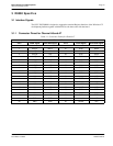
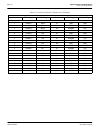
Table 2-2: Touchscreen Header (TS1) Pinout
Pin # Signal
1XR
2XL
3YU
4YL
5XY
6GND
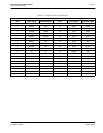
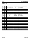
Table 2-3: Touchscreen Header Pinout
Jumper Function 1-2 2-3
LCDVCC1 LCD logic supply 3.3V
5V
FPS2 FPSHIFT2/DRDY/MOD
To pin 38 To pin 35
= default settings