


Page 126
Epson Research and Development
Vancouver Design Center
S1D13505 Hardware Functional Specification
X23A-A-001-14 Issue Date: 01/02/02
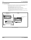
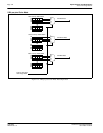
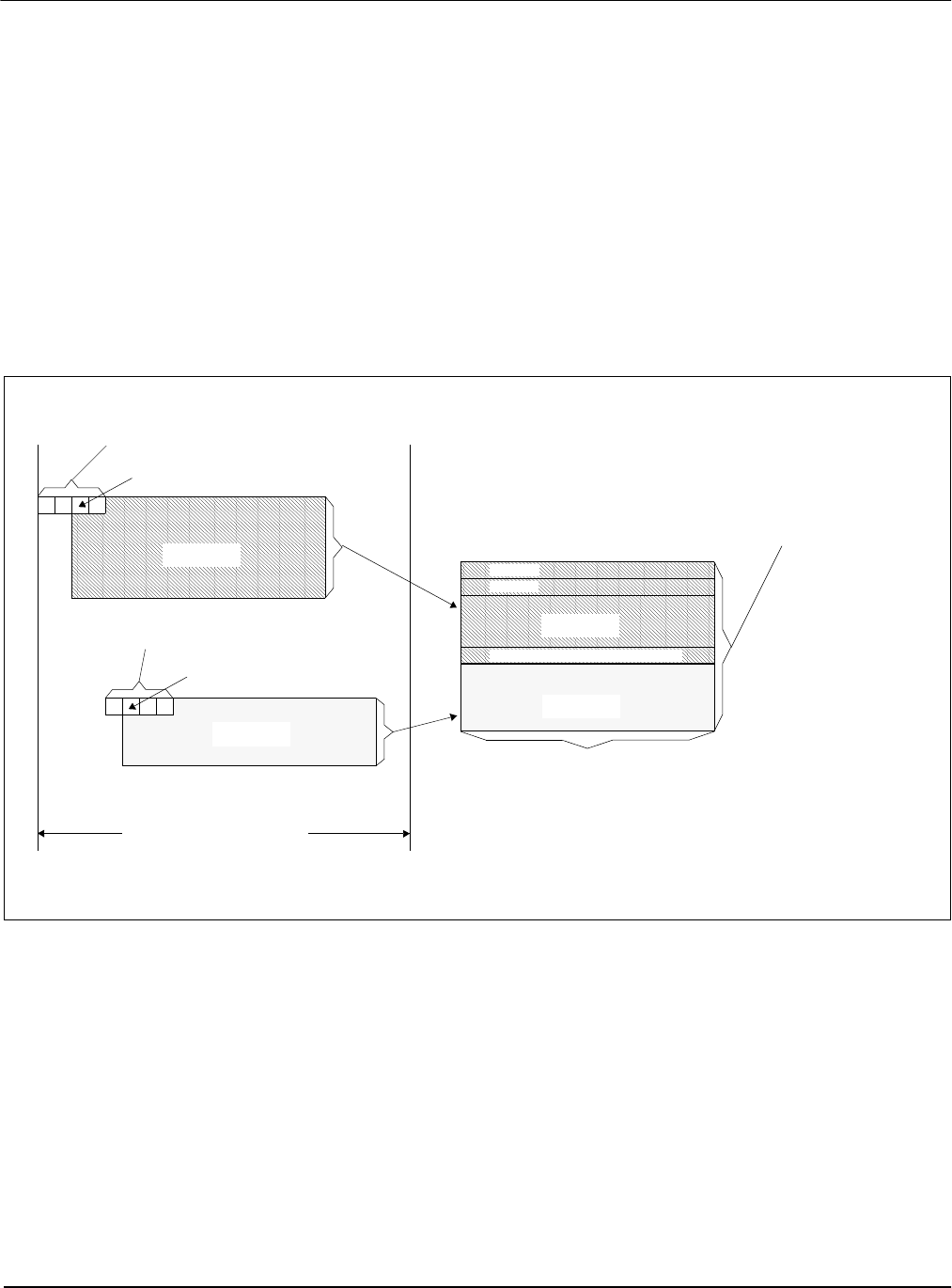
10.2 Image Manipulation
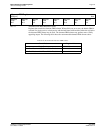
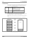
The figure below shows how Screen 1 and 2 images are stored in the image buffer and positioned
on the display. Screen 1 and Screen 2 can be parts of a larger virtual image or images.
• (REG[17h],REG[16h]) defines the width of the virtual image(s)
• (REG[12h],REG[11h],REG[10]) defines the starting word of the Screen 1,
(REG[15h],REG[14h],REG[13]) defines the starting word of the Screen 2
• REG[18h] bits [3:0] define the starting pixel within the starting word for Screen 1, REG[18h]
bits [7:4] define the starting pixel within the starting word for Screen 2
• (REG[0Fh],REG[0Eh]) define the last line of Screen 1, the remainder of the display is taken up
by Screen 2
Figure 10-3: Image Manipulation
(REG[17h], REG[16h])
(REG[15h], REG[14h], REG[13h])
REG[18h] bits [7:4]
(REG[12h], REG[11h], REG[10h])
REG[18h] bits [3:0]
((REG[04h]+1)*8) pixels
((REG[09h], REG[08h])+1) lines
Screen 2
Screen 1
Line (REG[0Fh], REG[0Eh])
Screen 2
Screen 1
Line 0
Line 1
DisplayImage Buffer