


Page 18
Epson Research and Development
Vancouver Design Center
S1D13505 Interfacing to the Motorola MPC821 Microprocessor
X23A-G-008-05 Issue Date: 01/02/05
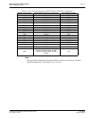
4.3 S1D13505 Hardware Configuration
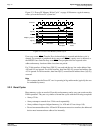
The S1D13505 latches MD15 through MD0 to allow selection of the bus mode and other
configuration data on the rising edge of RESET#. For details on configuration, refer to the
S1D13505 Hardware Functional Specification, document number X23A-A-001-xx.
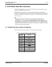
The following table shows those configuration settings important to the MPC821 host bus
interface.
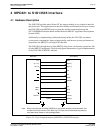
4.4 Register/Memory Mapping
The DRAM on the MPC821 ADS board extends from address 0 through 3F FFFFh, so the
S1D13505 is addressed starting at 40 0000h. A total of 4M bytes of address space is used,
where the lower 2M bytes is reserved for the S1D13505 on-chip registers and the upper 2M
bytes is used to access the S1D13505 display buffer.
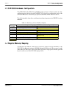
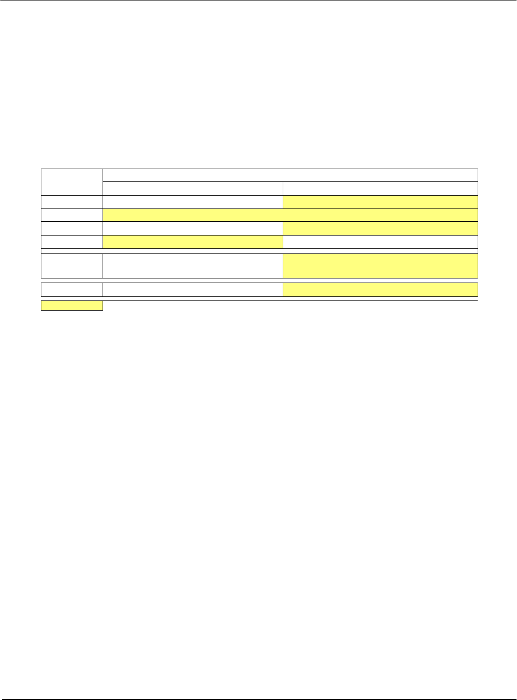
Table 4-2: Summary of Power-On/Reset Options
S1D13505
Pin Name
value on this pin at rising edge of RESET# is used to configure:
(1/0)
10
MD0 8-bit host bus interface
16-bit host bus interface
MD[3:1]
110 = PowerPC host bus interface selected
MD4 Little Endian Big Endian
MD5 Wait# signal is active high Wait# signal is active low
MD9 Reserved
Configure SUSPEND# pin as Hardware
Suspend Enable
MD11 Alternate Host Bus Interface Selected
Primary Host Bus Interface Selected
= required settings for MPC821 support.