


Page 118
Epson Research and Development
Vancouver Design Center
S1D13505 Hardware Functional Specification
X23A-A-001-14 Issue Date: 01/02/02
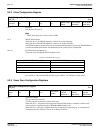
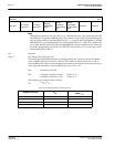
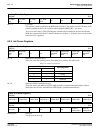
bits 7-4 LUT Data
This register is used to read/write the RGB Look-Up Tables. This register accesses the entry at the
pointer controlled by the Look-Up Table Address Register (REG[24h]) – see above.
Accesses to the Look-Up Table Data Register automatically increment the pointer.Note that the
RGB data is inserted into the LUT after the Blue data is written, i.e. all three colors must be written
before the LUT is updated.
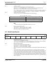
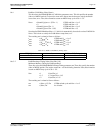
8.2.9 Ink/Cursor Registers
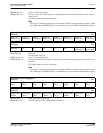
bit 7-6 Ink/Cursor Control Bits [1:0]
These bits select the operating mode of the Ink/Cursor circuitry. See table below
bit 3-0 Ink/Cursor FIFO Threshold Bits [3:0]
These bits specify the Ink/Cursor FIFO depth required to sustain uninterrupted display fetches.
When these bits are all 0, the Ink/Cursor FIFO depth is calculated automatically.
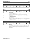
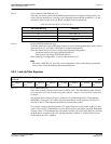
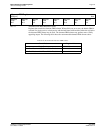
REG[29] bit 7 Reserved
This bit must be set to 0.
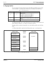
Look-Up Table Data Register
REG[26h] RW
LUT Data
Bit 3
LUT Data
Bit 2
LUT Data
Bit 1
LUT Data
Bit 0
n/an/an/an/a
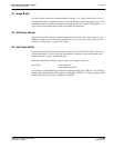
Ink/Cursor Control Register
REG[27h] RW
Ink/Cursor
Mode
Bit 1
Ink/Cursor
Mode
Bit 0
n/a n/a
Cursor High
Threshold
Bit 3
Cursor High
Threshold
Bit 2
Cursor High
Threshold
Bit 1
Cursor High
Threshold
Bit 0
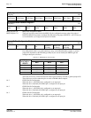
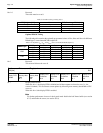
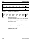
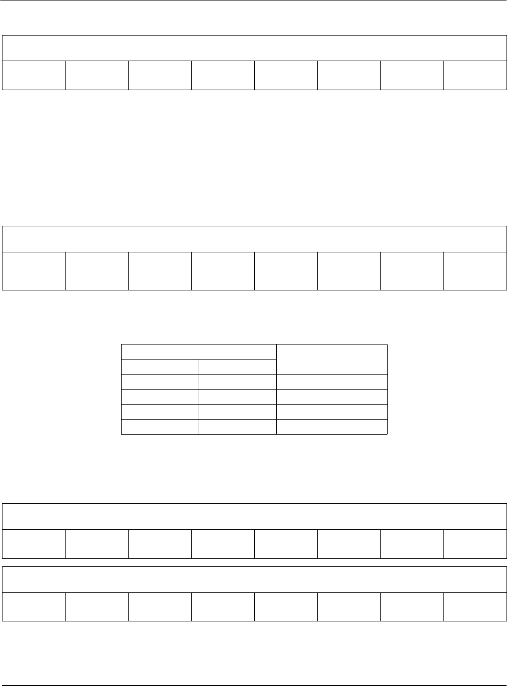
Table 8-17: Ink/Cursor Selection
REG[27h]
Operating Mode
Bit 7 Bit 6
00 inactive
01 Cursor
10 Ink
11reserved
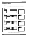
Cursor X Position Register 0
REG[28h] RW
Cursor X
Position Bit 7
Cursor X
Position Bit 6
Cursor X
Position Bit 5
Cursor X
Position Bit 4
Cursor X
Position Bit 3
Cursor X
Position Bit 2
Cursor X
Position Bit 1
Cursor X
Position Bit 0
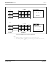
Cursor X Position Register 1
REG[29h] RW
Reserved n/a n/a n/a n/a n/a
Cursor X
Position Bit 9
Cursor X
Position Bit 8