


Page 134
Epson Research and Development
Vancouver Design Center
S1D13505 Hardware Functional Specification
X23A-A-001-14 Issue Date: 01/02/02
The image data for pixel n, (A
n
,B
n
), selects the color for pixel n as follows:
12.3 Ink/Cursor Image Manipulation
12.3.1 Ink Image
The Ink image should always start at the top left pixel, i.e. Cursor X Position and Cursor Y Position
registers should always be set to zero. The width and height of the ink image are automatically calcu-
lated to completely cover the display.
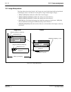
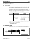
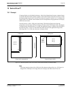
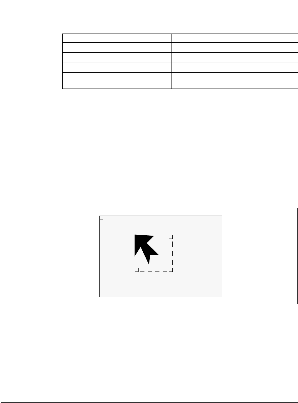
12.3.2 Cursor Image
The Cursor image size is always 64x64 pixels. The Cursor X Position and Cursor Y Position
registers specify the position of the top left pixel. The following diagram shows how to position a
cursor.
Figure 12-2: Cursor Positioning
where x = (REG[29h] bits [1:0], REG[28h]) REG[29h] bit 7 = 0
y = (REG[2Bh] bits [1:0], REG[2Ah]) REG[2Bh] bit 7 = 0
Note
There is no means to set a negative cursor position. If a cursor must be set to a negative position,
this must be dealt with through software.
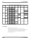
Table 12-2: Ink/Cursor Color Select
(A
n
,B
n
)Color Comments
00 Color 0
Ink/Cursor Color 0 Register, (REG[2Dh],REG[2Ch])
01 Color 1
Ink/Cursor Color 1 Register, (REG[2Fh],REG[2Eh])
10 Background
Ink/Cursor is transparent – show background
11 Inverted Background
Ink/Cursor is transparent – show inverted
background
P(0;0)
P(x;y) P(x+63;y)
P(x;y+63) P(x+63;y+63)