


Page 46
Epson Research and Development
Vancouver Design Center
S1D13505 Programming Notes and Examples
X23A-G-003-07 Issue Date: 01/02/05
Note
Bit 7 is write only, when reading back the register this bit reads a '0'.
7.3 Limitations
There are limitations for using the hardware cursor/ink layer which should be noted.
7.3.1 Updating Hardware Cursor Addresses
All hardware cursor addresses must be set during VNDP (vertical non-display period).
Check the VNDP status bit (REG[0Ah] bit 7) to determine if you are in VNDP, then update
the cursor address register.
7.3.2 Reg[29h] And Reg[2Bh]
Bit seven of registers [29h] and [2Bh] are write only, and must always be set to zero as
setting these bits to one, will cause undefined cursor behavior.
7.3.3 Reg [30h]
Bit 7 of register [30h] is write only, therefore programs cannot determine the current
cursor/ink layer start address by reading register [30h]. It is suggested that values written
to this register be stored elsewhere and used when the current state of this register is
required.
7.3.4 No Top/Left Clipping on Hardware Cursor
The S1D13505 does not clip the hardware cursor on the top or left edges of the display. For
cursor shapes where the hot spot is not the upper left corner of the image (the hourglass for
instance), the cursor image will have to be modified to clip the cursor shape.
7.4 Examples
See Section 12, “Sample Code” for hardware cursor programming examples.
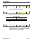
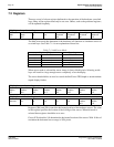
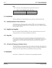
Table 7-2: Cursor/Ink Start Address Encoding
Ink/Cursor Start Address Bits [7:0] Start Address (Bytes)
0 Display Buffer Size - 1024
1 - FFh Display Buffer Size - (n * 8192)