


Page 44
Epson Research and Development
Vancouver Design Center
S1D13505 Programming Notes and Examples
X23A-G-003-07 Issue Date: 01/02/05
7.2 Registers
There are a total of eleven registers dedicated to the operation of the hardware cursor/ink
layer. Many of the registers need only be set once. Others, such as the positional registers,
will be updated frequently.
The Ink/Cursor mode bits determine if the hardware will function as a hardware cursor or
as an ink layer. See Table 7-1: for an explanation of these bits.
When cursor mode is selected the cursor image is always 64x64 pixels. Selecting an ink
layer will result in a large enough area to completely cover the display.
The cursor threshold bits are used to control the Ink/Cursor FIFO depth to sustain uninter-
rupted display fetches.
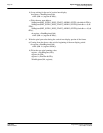
Registers [28h] and [29h] control the horizontal position of the hardware cursor. The value
in this register specifies the location of the left edge of the cursor. When ink mode is
selected these registers should be set to zero.
Cursor X Position bits 9-0 determine the horizontal location of the cursor. With 10 bits of
resolution the horizontal cursor range is 1024 pixels.
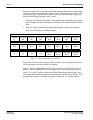
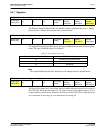
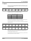
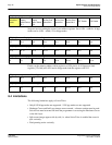
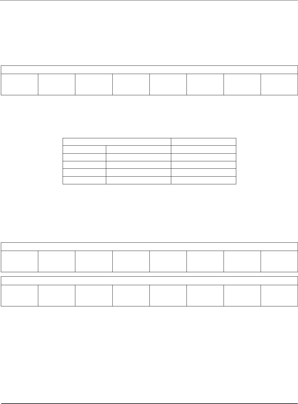
REG[27h] Ink/Cursor Control Register
Ink/Cursor
Mode
bit 1
Ink/Cursor
Mode
bit 0
n/a n/a
Cursor High
Threshold
bit 3
Cursor High
Threshold
bit 2
Cursor High
Threshold
bit 1
Cursor High
Threshold
bit 0
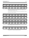
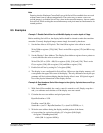
Table 7-1: Ink/Cursor Mode
Register [27h] Operating
bit 7 bit 6 Mode
0 0 Inactive
01 Cursor
10 Ink
11Reserved
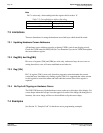
REG[28h] Cursor X Position Register 0
Cursor X
Position
bit 7
Cursor X
Position
bit 6
Cursor X
Position
bit 5
Cursor X
Position
bit 4
Cursor X
Position
bit 3
Cursor X
Position
bit 2
Cursor X
Position
bit 1
Cursor X
Position
bit 0
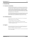
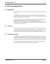
REG[29h] Cursor X Position Register 1
Reserved n/a n/a n/a n/a n/a
Cursor X
Position
bit 9
Cursor X
Position
bit 8