


Page 92
Epson Research and Development
Vancouver Design Center
S1D13505 Programming Notes and Examples
X23A-G-003-07 Issue Date: 01/02/05
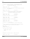
/*
** Register 19: Clock Configuration - In this case we must divide
** PCLK by 2 to arrive at the best frequency to set
** our desired panel frame rate.
*/
*(pRegs + 0x19) = 0x01; /* 0000 0001 */
/*
** Register 1A: Power Save Configuration - enable LCD power, CBR refresh,
** not suspended.
*/
*(pRegs + 0x1A) = 0x00; /* 0000 0000 */
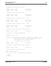
/*
** Register 1C-1D: MD Configuration Readback - these registers are
** read only, but it's OK to write a 0 to keep
** the register configuration logic simpler.
*/
*(pRegs + 0x1C) = 0x00; /* 0000 0000 */
*(pRegs + 0x1D) = 0x00; /* 0000 0000 */
/*
** Register 1E-1F: General I/O Pins Configuration
*/
*(pRegs + 0x1E) = 0x00; /* 0000 0000 */
*(pRegs + 0x1F) = 0x00; /* 0000 0000 */
/*
** Register 20-21: General I/O Pins Control
*/
*(pRegs + 0x20) = 0x00; /* 0000 0000 */
*(pRegs + 0x21) = 0x00; /* 0000 0000 */
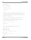
/*
** Registers 24-26: LUT control.
** For this example do a typical 8 BPP LUT setup.
**
** Setup the pointer to the LUT data and reset the LUT index register.
** Then, loop writing each of the RGB LUT data elements.
*/
pLUT = LUT8;
*(pRegs + 0x24) = 0;
for (idx = 0; idx < 256; idx++)
{
for (rgb = 0; rgb < 3; rgb++)
{
*(pRegs + 0x26) = *pLUT;
pLUT++;
}
}
/*
** Register 27: Ink/Cursor Control - disable ink/cursor
*/
*(pRegs + 0x27) = 0x00; /* 0000 0000 */