


Epson Research and Development
Page 13
Vancouver Design Center
Interfacing to the PC Card Bus S1D13505
Issue Date: 01/02/05 X23A-G-005-06
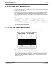
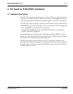
4 PC Card to S1D13505 Interface
4.1 Hardware Description
The S1D13505 is designed to directly support a variety of CPUs, providing an interface to
each processor’s unique “local bus”. However, in order to provide support for processors
not having an appropriate local bus, the S1D13505 supports a specific PC Card interface.
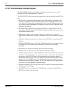
The S1D13505 provides a “glueless” interface to the PC Card bus except for the following.
• The RESET# signal on the S1D13505 is active low and must be inverted to support the
active high RESET provided by the PC Card interface.
• Although the S1D13505 supports an asynchronous bus interface, a clock source is
required on the BUSCLK input pin.
In this implementation, the address inputs (AB[20:0]) and data bus (DB[15:0]) connect
directly to the CPU address (A[20:0]) and data bus (D[15:0]). M/R# is treated as an address
line so that it can be controlled using system address A21.
The PC Card interface does not provide a bus clock, so one must be supplied for the
S1D13505. Since the bus clock frequency is not critical, nor does it have to be synchronous
to the bus signals, it may be the same as CLKI. BS# (bus start) is not used and should be
tied high (connected to V
DD
).