


Epson Research and Development
Page 81
Vancouver Design Center
Hardware Functional Specification S1D13505
Issue Date: 01/02/02 X23A-A-001-14
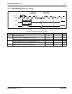
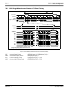
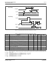
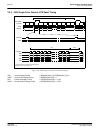
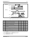
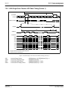
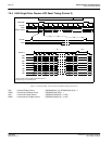
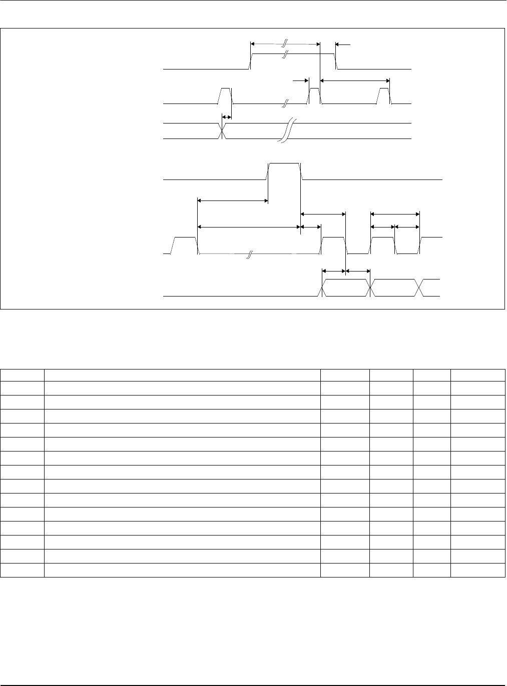
Figure 7-29: 4-Bit Single Color Passive LCD Panel A.C. Timing
1. Ts = pixel clock period = memory clock, [memory clock]/2, [memory clock]/3, [memory clock]/4 (see REG[19h] bits [1:0])
2. t1
min
= t4
min
- 14Ts
3. t4
min
= [((REG[04h] bits [6:0])+1)*8 + ((REG[05h] bits [4:0]) + 1)*8] + 33 Ts
4. t5
min
=[(((REG[04h] bits [6:0])+1)*8 + ((REG[05h] bits [4:0]) + 1)*8)-1] Ts
5. t6
min
= [((REG[05h] bits [4:0]) + 1)*8 - 28] Ts
6. t9
min
= [((REG[05h] bits [4:0]) + 1)*8 - 19] Ts
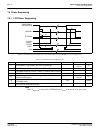
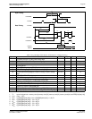
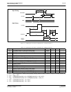
Table 7-25: 4-Bit Single Color Passive LCD Panel A.C. Timing
Symbol Parameter Min Typ Max Units
t1
FPFRAME setup to FPLINE pulse trailing edge
note 2
t2
FPFRAME hold from FPLINE pulse trailing edge
14 Ts (note 1)
t3
FPLINE pulse width
9Ts
t4
FPLINE period
note 3
t5
MOD transition to FPLINE pulse trailing edge
1note 4Ts
t6
FPSHIFT falling edge to FPLINE pulse leading edge
note 5
t7
FPLINE pulse trailing edge to FPSHIFT falling edge
t10 + t11 Ts
t8
FPSHIFT period
1Ts
t9
FPSHIFT falling edge to FPLINE pulse trailing edge
note 6
t10
FPLINE pulse trailing edge to FPSHIFT rising edge
21 Ts
t11
FPSHIFT pulse width high
0.45 Ts
t12
FPSHIFT pulse width low
0.45 Ts
t13
UD[3:0], setup to FPSHIFT falling edge
0.45 Ts
t14
UD[3:0], hold from FPSHIFT falling edge
0.45 Ts
FPFRAME
FPLINE
MOD
Sync Timing
FPLINE
FPSHIFT
UD[3:0]
Data Timing
t5
t10
t1
t2
t4
t3
t7
t8
t12t11
t13
t14
1
2
t9
t6