


Epson Research and Development
Page 13
Vancouver Design Center
Evaluation Board User Manual S5U13505-D9000
Issue Date: 01/02/05 X23A-G-002-04
3 D9000 Specifics
3.1 Interface Signals
The S5U13505-D9000 is designed to support the standard Register Interface of the Windows CE
development platform together with the FPGA code that comes with the board.
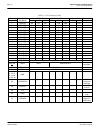
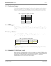
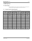
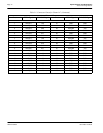
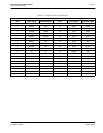
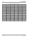
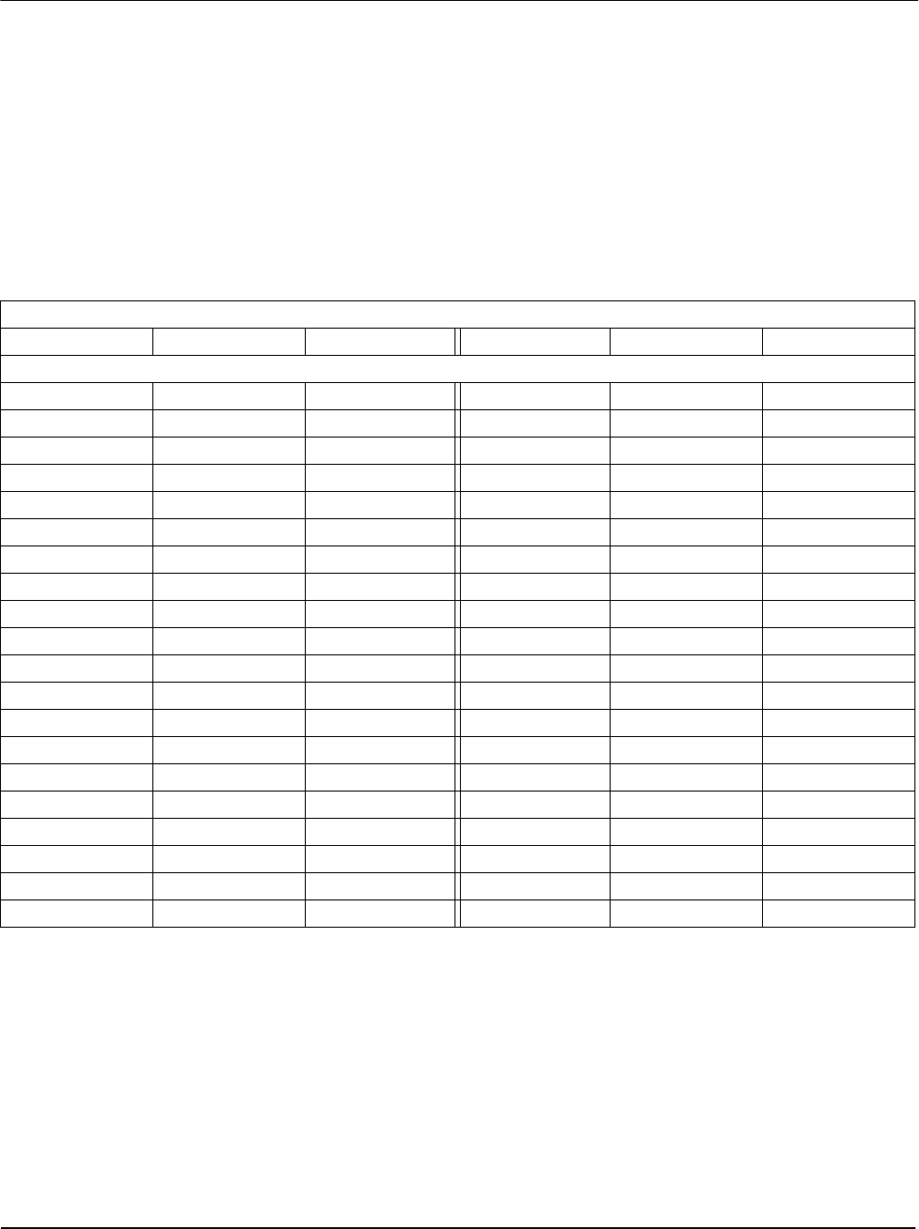
3.1.1 Connector Pinout for Channel A6 and A7
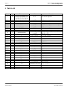
Table 3-1: Connectors Pinout for Channel A7
Channel A7
Pin # FPGA Signal S1D13505 Signal Pin # FPGA Signal S1D13505 Signal
SmXY
1 chA7p1 BCLK 21 dc5v DC5V
2 chA7p2 N/C 22 GND GND
3 chA7p3 N/C 23 dc3v DC3V
4 chA7p4 N/C 24 GND GND
5 chA7p5 N/C 25 dc3v DC3V
6 chA7p6 N/C 26 GND GND
7 chA7p7 N/C 27 dc3vs N/C
8 chA7p8 N/C 28 GND GND
9 chA7p9 N/C 29 dc12v DC12V
10 chA7p10 N/C 30 GND GND
11 ib8 N/C 31 battery N/C
12 ib7 N/C 32 GND GND
13 ib6 N/C 33 dcXA N/C
14 ib5 N/C 34 base5vDc N/C
15 ib4 N/C 35 dcXB N/C
16 ib3 N/C 36 GND GND
17 ib2 N/C 37 dcXC N/C
18 ib1 N/C 38 GND GND
19 GND GND 39 senseH N/C
20 GND GND 40 senseL N/C