


Page 12
Epson Research and Development
Vancouver Design Center
S1D13505 Interfacing to the NEC V832™ Microprocessor
X23A-G-012-02 Issue Date: 01/02/05
4 V832 to S1D13505 Interface
4.1 Hardware Description
The NEC V832 microprocessor features configurable chip select lines which can easily be
used for an external LCD controller. It provides all the necessary internal address decoding
and control signals required by the S1D13505.
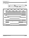
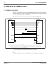
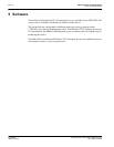
The diagram below shows a typical implementation utilizing the S1D13505.
Figure 4-1: NEC V832 to S1D13505 Configuration Schematic
Note
For pin mapping see Table 3-1:, “Host Bus Interface Pin Mapping,” on page 10.
WE1#
WE0#
DB[15:0]
WAIT#
RD#
BUSCLK
S1D13505
CS#
M/R#
RESET#
AB[20:1]
A21
LUBEN
IOWR
D[15:0]
CSn
IORD
SDCLKOUT
READY
A[25:1]
NEC V832
Pull-up
BS#
V
DD
V
DD
(+3.3V)
System RESET
AB0
VDD_O
+3.3V
+2.5V
VDD_I
RD/WR#
LLBEN
When connecting the S1D13505 RESET# pin, the system designer should be aware of all
conditions that may reset the S1D13505 (e.g. CPU reset can be asserted during wake-up
from power-down modes, or during debug states).
Note: