


Page 10
Epson Research and Development
Vancouver Design Center
S1D13505 Interfacing to the NEC V832™ Microprocessor
X23A-G-012-02 Issue Date: 01/02/05
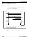
3 S1D13505 Host Bus Interface
The S1D13505 directly supports multiple processors. The S1D13505 implements a 16-bit
PC Card (PCMCIA) Host Bus Interface which is most suitable for direct connection to the
V832 microprocessor.
The PC Card host bus interface is selected by the S1D13505 on the rising edge of RESET#.
After releasing reset the bus interface signals assume their selected configuration. For
details on S1D13505 configuration, see Section 4.2, “S1D13505 Hardware Configuration”
on page 13.
Note
At reset, the Host Interface Disable bit in the Miscellaneous Disable Register
(REG[1Bh] bit 7) is set to 1. This means that only REG[1Ah] (read-only) and
REG[1Bh] are accessible until a write to REG[1Bh] sets bit 7 to 0 making all regis-
ters accessible. When debugging a new hardware design, this can sometimes give the
appearance that the interface is not working, so it is important to remember to clear this
bit before proceeding with debugging.
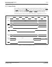
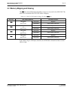
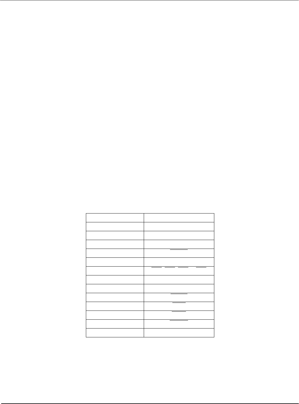
3.1 Host Bus Interface Pin Mapping
The following table shows the functions of each host bus interface signal.
Note
1
The bus signal A0 is not used by the S1D13505 internally.
Table 3-1: Host Bus Interface Pin Mapping
S1D13505 Pin Name NEC V832 Pin Name
AB[20:1] A[20:1]
A0 GND
1
DB[15:0] D[15:0]
WE1# LUBEN
M/R# A21
CS# CS3
, CS4, CS5 or CS6
BUSCLK SDCLKOUT
BS# Connected to VDD (+3.3V)
RD/WR# LLBEN
RD# IORD
WE0# IOWR
WAIT# READY
RESET# connected to system reset