


Epson Research and Development
Page 137
Vancouver Design Center
Hardware Functional Specification S1D13505
Issue Date: 01/02/02 X23A-A-001-14
13.3 Physical Memory Requirement
Because the programmer must now deal with a virtual display, the amount of image buffer required
for a particular display mode has increased. The minimum amount of image buffer required is:
Minimum Required Image Buffer (bytes)
=(1024
×
H)
×
2 for 16 bpp mode
=(1024
×
H) for 8 bpp mode
For single panel, the required display buffer size is the same as the image buffer required. For dual
panel, the display buffer required is the sum of the image buffer required and the half-frame buffer
memory required. The half-frame buffer memory requirement is:
Half-Frame Buffer Memory (bytes)
=(W
×
H) / 4 for color mode
=(W
×
H) / 16 for monochrome mode
The half-frame buffer memory is always located at the top of the physical memory.
For simplicity the hardware cursor and ink layer memory requirement is ignored. The hardware
cursor and ink layer memory must be located at 16K byte boundaries and it must not overlap the
image buffer and half-frame buffer memory areas.
Even though the virtual display is 1024
×
1024 pixels, the actual panel window is always smaller.
Thus it is possible for the display buffer size to be smaller than the virtual display but large enough
to fit both the required image buffer and the half-frame buffer memory. This poses a maximum
“accessible” horizontal virtual size limit.
Maximum Accessible Horizontal Virtual Size (pixels)
= (Physical Memory – Half-Frame Buffer Memory) / 2048 for 16 bpp mode
= (Physical Memory – Half-Frame Buffer Memory) / 1024 for 8 bpp mode
For example, a 640
×
480 single panel running 8 bpp mode requires 480K byte of image buffer and
0K byte of half-frame buffer memory. The virtual display size is 1024
×
1024 = 1M byte. The
programmer may use a 512K byte DRAM which is smaller than the 1M byte virtual display but
greater than the 480K byte minimum required image buffer. The maximum accessible horizontal
virtual size is = (512K byte - 0K byte) / 1024 = 512. The programmer therefore has room to pan the
portrait window to the right by 512 - 480 = 32 pixels. The programmer also should not read/write to
the memory beyond the maximum accessible horizontal virtual size because that memory is either
reserved for the half-frame buffer or not associated with any real memory at all.
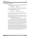
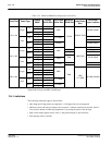
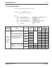
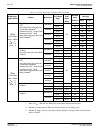
The following table summarizes the DRAM size requirement for SwivelView using different panel
sizes and display modes. Note that DRAM size for the S1D13505 is limited to either 512K byte or
2M byte. The calculation is based on the minimum required image buffer size. The calculated
minimum display buffer size is based on the image buffer and the half-frame buffer only; it does not
take into account the hardware cursor/ink layer and so it may or may not be sufficient to support it
– this is noted in the table. The hardware cursor requires 1K byte of memory and the 2-bit ink layer
requires (W
×
H) / 4 bytes of memory; both must reside at 16K byte boundaries but only one is
supported at a time. The table shows only one possible sprite/ink layer location – at the highest
possible 16K byte boundary below the half-frame buffer which is always at the top.