


Page 8
Epson Research and Development
Vancouver Design Center
S1D13505 S5U13505B00C Rev. 1.0 ISA Bus Evaluation Board User Manual
X23A-G-004-05 Issue Date: 01/02/05
2 Installation and Configuration
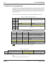
The S1D13505 has 16 configuration inputs MD[15:0] which are read on the rising edge of RESET#.
Inputs MD[5:1] are fully configurable on this evaluation board for different host bus selections; one
eight-position DIP switch is provided for this purpose. All remaining configuration inputs are hard-
wired. See the S1D13505 Hardware Functional Specification, document number X23A-A-001-xx
for more information.
The following settings are recommended when using the S5U13505B00C with the ISA bus.
Note
JP1 is for internal use only, default setting is 1-2.
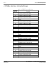
Table 2-1: Configuration DIP Switch Settings
Switch Signal Closed (1) Open (0)
SW1-1 MD1
See “Host Bus Selection” table below See “Host Bus Selection” table belowSW1-2 MD2
SW1-3 MD3
SW1-4 MD4
Little Endian Big Endian
SW1-5 MD5 Wait# signal is active high
Wait# signal is active low
SW1-6 MD13
ReservedSW1-7 MD14
SW1-8 MD15
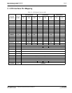
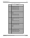
Table 2-2: Host Bus Selection
MD3 / SW1-3 MD2 / SW1-2 MD1 / SW1-1 Host Bus Interface
open (0) open (0) open (0)
SH-3/SH-4 bus interface
open (0) open (0) closed (1)
MC68K bus 1 interface (e.g. MC68000)
open (0) closed (1) open (0)
MC68K bus 2 interface (e.g. MC68030)
open (0) closed (1) closed (1)
Generic bus interface
closed (1) open (0) open (0)
Reserved
closed (1) open (0) closed (1)
MIPS/ISA
closed (1) closed (1) open (0)
PowerPC
closed (1) closed (1) closed (1)
PC Card (PCMCIA)
= recommended settings (configured for ISA bus support)
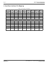
Table 2-3: Jumper Settings
Description 1-2 2-3
JP1
DRDY (pin 76, S1D13505) Pin 76 connected to J6 pin 38 Pin 76 connected to J6 pin 35
JP2
LCD V
DD
Selection 5.0V
LCD driver V
DD
3.3V
LCD driver V
DD