


Epson Research and Development
Page 17
Vancouver Design Center
S5U13505B00C Rev. 1.0 ISA Bus Evaluation Board User Manual S1D13505
Issue Date: 01/02/05 X23A-G-004-05
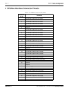
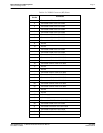
6.13 CPU/Bus Interface Header Strips
All of the CPU/Bus interface pins of the S1D13505 are connected to the header strips H1 and H2 for
easy interface to a CPU, or bus other than ISA.
Refer to Table 4-1 “CPU/BUS Connector (H1) Pinout” on page 10 and Table 4-2 “CPU/BUS
Connector (H2) Pinout” on page 11 for specific settings.
Note
These headers only provide the CPU/Bus interface signals from the S1D13505. When another
host bus interface is selected through [MD3:1] configuration, appropriate external decode logic
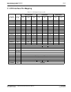
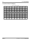
MUST be used to access the S1D13505. See the section “Host Bus Interface Pin Mapping” of the
S1D13505 Hardware Functional Specification, document number X23A-A-001-xx.
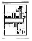
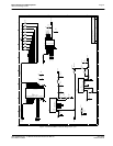
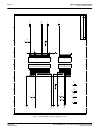
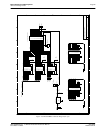
6.14 Schematic Notes
The following schematics are for reference only and may not reflect actual implementation. Please
request updated information before starting any hardware design.