


Epson Research and Development
Page 37
Vancouver Design Center
Programming Notes and Examples S1D13505
Issue Date: 01/02/05 X23A-G-003-07
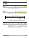
5.3.2 Examples
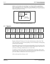
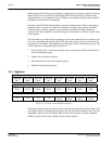
Example 6:Display 380 scanlines of image 1 and 100 scanlines of image 2. Image 2
is located immediately after image 1 in the display buffer. Assume a
640x480 display and a color depth of 1 bpp.
1. The value for the line compare is not dependent on any other setting so we can set it
immediately (380 = 17Ch).
Write the line compare registers [0Fh] with 01h and register [0Eh] with 7Ch.
2. Screen 1 is coming from offset 0 in the display buffer. Although not necessary, ensure
that the screen 1 start address is set to zero.
Write 00h to registers [10h], [11h] and [12h].
3. Calculate the size of the screen 1 image (so we know where the screen 2 image is lo-
cated). This calculation must be performed on the virtual size (offset register) of the
display. Since a virtual size was not specified assume the virtual size to be the same as
the physical size.
offset = pixels_per_line / pixels_per_word = 640 / 16 = 40 words per line
screen1_size = offset * lines = 40 * 480 = 19,200 words = 4B00h words
4. Set the screen 2 start address to the value we just calculated.
Write the screen 2 start address registers [15h], [14h] and [13h] with the values 00h,
4Bh and 00h respectively.