


Epson Research and Development
Page 133
Vancouver Design Center
Hardware Functional Specification S1D13505
Issue Date: 01/02/02 X23A-A-001-14
12 Ink/Cursor Architecture
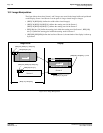
12.1 Ink/Cursor Buffers
The Ink/Cursor buffers contain formatted image data for the Ink Layer or Hardware Cursor. There
may be several Ink/Cursor images stored in the display buffer but only one may be active at any
given time.
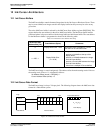
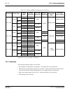
The active Ink/Cursor buffer is selected by the Ink/Cursor Start Address register (REG[30h]). This
register defines the start address for the active Ink/Cursor buffer. The Ink/Cursor buffer must be
positioned where it does not conflict with the image buffer and half-frame buffer. The start address
for the Ink/Cursor buffer is programmed as shown in the following table:
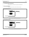
The Ink/Cursor image is stored contiguously. The address offset from the starting word of line
n
to
the starting word of line
n+1
is calculated as follows:
Ink Address Offset (words) = REG[04h] + 1
Cursor Address Offset (words) = 8
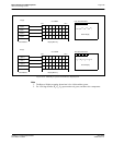
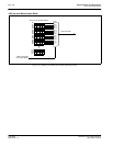
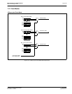
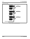
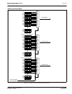
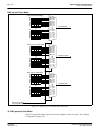
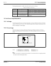
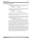
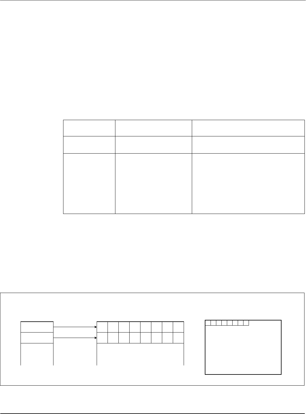
12.2 Ink/Cursor Data Format
The Ink/Cursor image is always 2 bit-per-pixel. The following diagram shows the Ink/Cursor data
format for a little-endian system.
Figure 12-1: Ink/Cursor Data Format
Table 12-1: Ink/Cursor Start Address Encoding
Ink/Cursor Start
Address Bits [7:0]
Start Address (Bytes) Comments
0 Display Buffer Size - 1024
This default value is suitable for a cursor
when there is no half-frame buffer.
n = 255...1
Display Buffer Size -
(n
×
8192)
These positions can be used to:
• position an Ink buffer at the top of the
display buffer;
• position an Ink buffer between the image
and half-frame buffers;
• position a Cursor buffer between the image
and half-frame buffers;
• select from a multiple of Cursor buffers.
2 bpp:
A
0
B
0
A
1
B
1
A
2
B
2
A
3
B
3
Host Address
Ink/Cursor Buffer
A
4
B
4
A
5
B
5
A
6
B
6
A
7
B
7
bit 7 bit 0
Byte 0
Byte 1
Panel Display
P
0
P
1
P
2
P
3
P
4
P
5
P
6
P
7
P
n
= (A
n
, B
n
)