


Page 120
Epson Research and Development
Vancouver Design Center
S1D13505 Hardware Functional Specification
X23A-A-001-14 Issue Date: 01/02/02
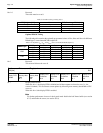
REG[2E] bits 7:0 Ink/Cursor Color 1 Bits [15:0]
REG[2F] bits 7:0 These bits define the 5-6-5 RGB Ink/Cursor color 1
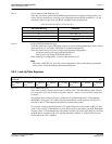
bits 7-0 Ink/Cursor Start Address Select Bits [7:0]
These bits define the start address for the Ink/Cursor buffer. The Ink/Cursor buffer must be posi-
tioned where it does not conflict with the image buffer and half-frame buffer – see Memory Map-
ping for details.
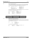
The start address for the Ink/Cursor buffer is programmed as shown in the following table where
Display Buffer Size represents the size in bytes of the attached DRAM device (see MD[7:6] in
Summary of Configuration Options
):
The Ink/Cursor image is stored contiguously. The address offset from the starting word of line n to
the starting word of line n+1 is calculated as follows:
Ink Address Offset (words) = REG[04h] + 1
C
ursor Address Offset (words) = 8
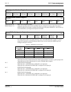
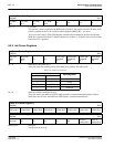
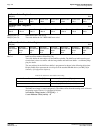
Ink/Cursor Color 1 Register 0
REG[2Eh] RW
Cursor Color
1 Bit 7
Cursor Color
1 Bit 6
Cursor Color
1 Bit 5
Cursor Color
1 Bit 4
Cursor Color
1 Bit 3
Cursor Color
1 Bit 2
Cursor Color
1 Bit 1
Cursor Color
1 Bit 0
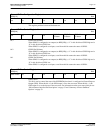
Ink/Cursor Color 1 Register 1
REG[2Fh] RW
Cursor Color
1 Bit 15
Cursor Color
1 Bit 14
Cursor Color
1 Bit 13
Cursor Color
1 Bit 12
Cursor Color
1 Bit 11
Cursor Color
1 Bit 10
Cursor Color
1 Bit 9
Cursor Color
1 Bit 8
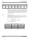
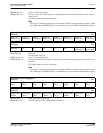
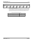
Ink/Cursor Start Address Select Register
REG[30h] RW
Ink/Cursor
Start Address
Select
Bit 7
Ink/Cursor
Start Address
Select
Bit 6
Ink/Cursor
Start Address
Select
Bit 5
Ink/Cursor
Start Address
Select
Bit 4
Ink/Cursor
Start Address
Select
Bit 3
Ink/Cursor
Start Address
Select
Bit 2
Ink/Cursor
Start Address
Select
Bit 1
Ink/Cursor
Start Address
Select
Bit 0
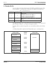
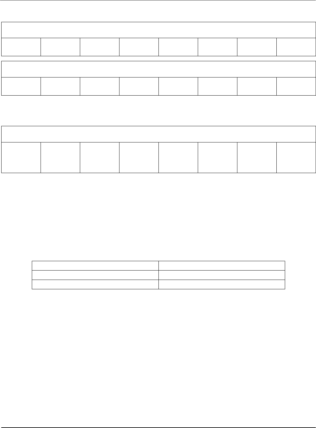
Table 8-18: Ink/Cursor Start Address Encoding
Ink/Cursor Start Address Bits [7:0] Start Address (Bytes)
0 Display Buffer Size - 1024
n = 255...1 Display Buffer Size - (n
×
8192)