


Epson Research and Development
Page 11
Vancouver Design Center
Interfacing to the Philips MIPS PR31500/PR31700 Processor S1D13505
Issue Date: 01/02/05 X23A-G-001-07
4 Direct Connection to the Philips PR31500/PR31700
The S1D13505 was specifically designed to support the Philips MIPS PR31500/PR31700
processor. When configured, the S1D13505 will utilize one of the PC Card slots supported
by the processor.
4.1 Hardware Description
In this example implementation, the S1D13505 occupies one PC Card slot and resides in
the Attribute and IO address range. The processor provides address bits A[12:0], with
A[23:13] being multiplexed and available on the falling edge of ALE. Peripherals requiring
more than 8K bytes of address space would require an external latch for these multiplexed
bits. However, the S1D13505 has an internal latch specifically designed for this processor
making additional logic unnecessary. To further reduce the need for external components,
the S1D13505 has an optional BUSCLK divide-by-2 feature, allowing the high speed
DCLKOUT from the processor to be directly connected to the BUSCLK input of the
S1D13505. An optional external oscillator may be used for BUSCLK since the S1D13505
will accept host bus control signals asynchronously with respect to BUSCLK.
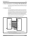
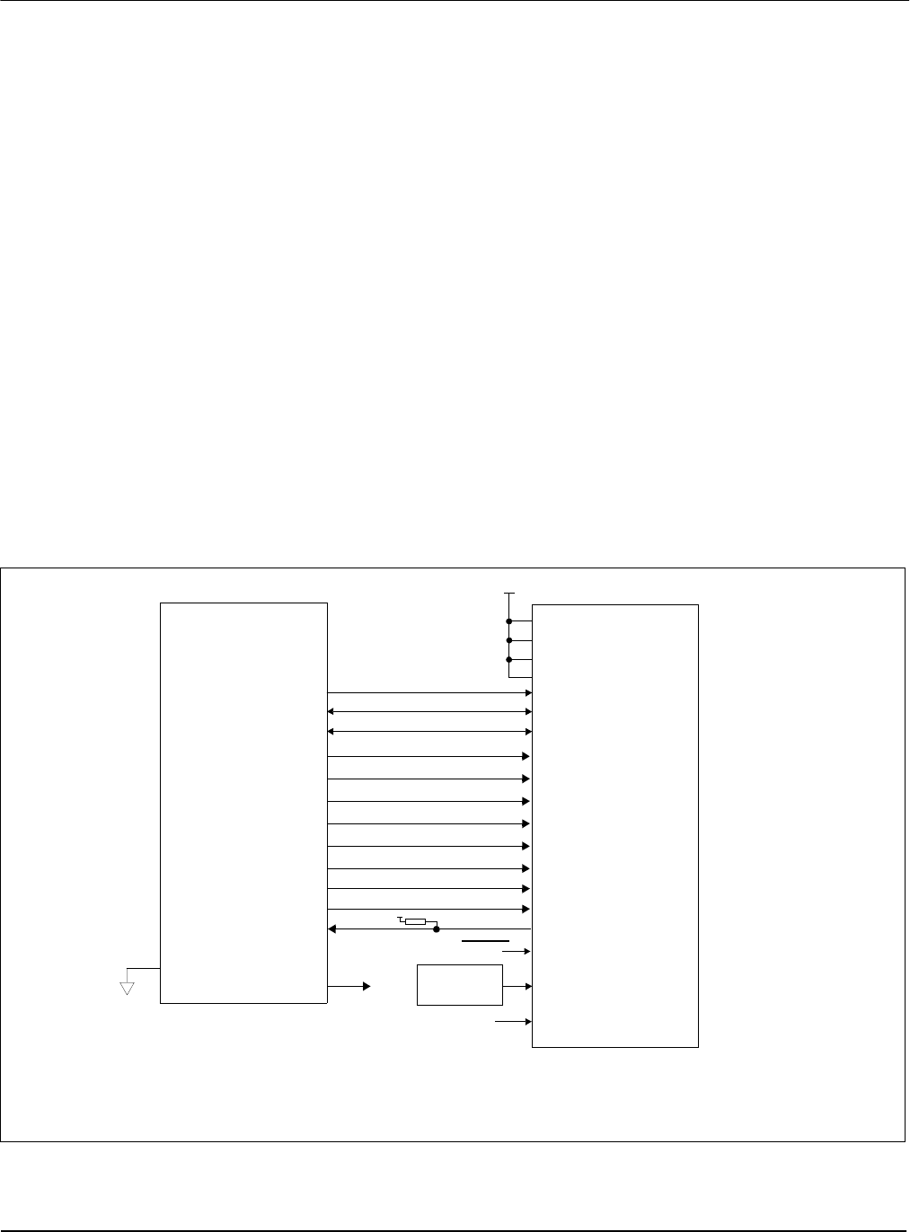
The following diagram shows a typical implementation of the interface.
Figure 4-1: Typical Implementation of Direct Connection
PR31500/PR31700
/WE
D[31:24]
/CARDxCSL
/RD
/CARDxWAIT
A[12:0]
DCLKOUT
WE0#
RD/WR#
AB[12:0]
DB[7:0]
WE1#
BS#
RD#
M/R#
CS#
BUSCLK
WAIT#
RESET#
/CARDxCSH
AB[16:13]
ALE
/CARDREG
/CARDIORD
AB20
AB19
AB18
AB17
/CARDIOWR
S1D13505
D[23:16]
DB[15:8]
ENDIAN
V
DD
(+3.3V)
System RESET
pull-up
V
DD
Oscillator
...or...
CLKI
See text
When connecting the S1D13505 RESET# pin, the system designer should be aware of all
conditions that may reset the S1D13505 (e.g. CPU reset can be asserted during wake-up
from power-down modes, or during debug states).
Note: