


RealPresence Collaboration Server (RMX) 1500/2000/4000 Administrator’s Guide
5-4 Polycom, Inc.
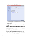
The tone volume is controlled by the same flag as the IVR messages and tones:
IVR_MESSAGE_VOLUME.
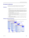
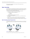
Basic Cascading
In this topology, a link is created between two conferences, usually running on two different
MCUs. The MCUs are usually installed at different locations (states/countries) to save long
distance charges by connecting each participant to their local MCU, while only the link
between the two conferences is billed as long distance call.
• This is the only topology that enables both IP and ISDN cascading links.
• When linking two conferences using an IP cascading link:
— The destination MCU can be indicated by:
•IP address
• H.323 Alias
— Both MCUs must be located in the same network.
• One MCU can be used as a gateway.
• The configuration can include two Collaboration Servers or one Collaboration Server
and one MGC.
• Multiple Cascade Links enabling Cascading between RMXs hosting conferences that
include Immersive Telepresence Rooms (ITP) such as Polycom’s OTX and RPX Room
Systems can be defined. For more information see "Multiple Cascade Links” on page 4-63.
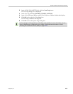
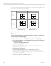
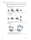
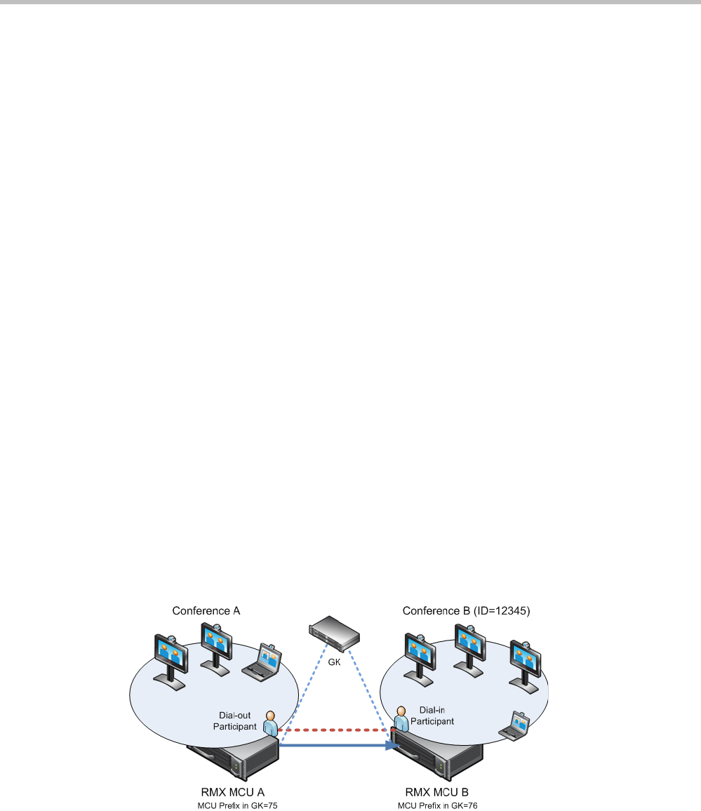
Basic Cascading using IP Cascaded Link
In this topology, both MCUs can be registered with the same gatekeeper or the IP addresses
of both MCUs can be used for the cascading link. Content can be sent across the Cascading
Link.
Figure 5-2 Basic Cascading Topology - IP Cascading Link
For example, MCU B is registered with the gatekeeper using 76 as the MCU prefix.