


Chapter 5-Cascading Conferences
Polycom, Inc. 5-33
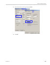
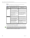
• Setting the AVOID_VIDEO_LOOP_BACK_IN_CASCADE System Flag to YES
(default) prevents the speaker’s image from being sent back through the participant
link from the cascaded conference. This can occur in cascaded conferences with
conference layouts other than 1x1. It results in the speaker’s own video image being
displayed in the speaker’s video layout.
This option is supported with:
— In H.323, SIP and ISDN environments.
— For Basic Cascading of Continuous Presence and Video Switched conferences. If a
Master MCU has two slave MCUs, participants connected to the slave MCUs will
not receive video from each other.
— Video resolution will be according to the Resolution Configuration, or VSW profile.
For more details on defining system flags, see "Modifying System Flags” on page 22-1.
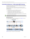
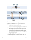
MGC to Collaboration Server Cascading
If MGC is running version 9.0.4, and Collaboration Server is running version 7.0.2 and
higher, the Collaboration Server can be set as Master on level 1 and MGC as Slave on level 2.
MGC running versions other than 9.0.4 is always on level 1 and must be set as the Master
MCU.
If the cascading topology includes additional MGCs as well as Collaboration Servers it is
recommended to define Video Switching conferences for all the cascading conferences
running on the MGC in the topology.
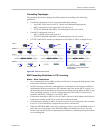
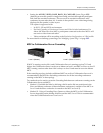
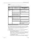
Two methods can be used to create the Cascading links between conferences running on the
Collaboration Server and MGC:
• Method I - Establish the links by defining a dial-in and a dial-out participant in the
Slave and Master conference (where the Master conference is created on the MCU on
Level 1 and the Slave conference is created on the MCU on Level 2).
• Method II - Using a Cascading Entry Queue on either the MGC or the Collaboration
Server depending on the dialing direction and the MCU Level. This is recommended
when the Collaboration Server is on Level 1.
Level 1 (Master)
Level 2 (Slave to Level 1)