


CT1/PRI Interface 135
By default, the functions of internal loopback and external loopback are disabled
on the CE1/PRI interface.
Display and Debug
CE1/PRI Interface
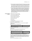
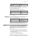
Perform the following configurations in all views to display the status and related
information of the CE1/PRI interface, so as to monitor and maintain it.
Table 136 Display and debug CE1/PRI interface
Generally, CE1/PRI interface is applied to the dedicated line and dial-up services.
For the typical configuration example and troubleshooting, refer to the
configurations of protocols at each layer and dialing configurations in this manual.
CT1/PRI Interface Along with the emergence of Pulse Code Modulation (PCM) technique in the
1960s, Time Division Multiplexing (TDM) technique is eventually achieving broad
applications in the digital communication systems. The TDM system is divided into
two types: T1 system recommended by ANSI and E1 system recommended by
ITU-T. The former one is mainly applied in North America and Japan (the J1 system
adopted in Japan is similar to the T1 system and hence can be taken as T1 system),
and the latter is widely applied in Europe and China.
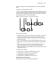
T1 line is comprised of 24 multiplexed channels. In other words, one T1 primary
frame DS1 contains 24 DS0 (64kbps) timeslots, each of them has 8 bits, and other
1 bit is taken as the framing bit. As a result, each primary frame has 193 bits. This
value can be got as follows: 24 x 8 + 1=193 bits. Since 8000 frames can be sent
per second, the transmission speed of DS1 is 193 x 8K = 1.544 Mbps.
The CT1/PRI interface can only operate in channelized operating mode. It is used
in the following two ways:
■ When the interface is used as a CT1 interface, all the timeslots from 1 to 24
can be divided into multiple groups at will, and each group can be bound to
form a channel set. Upon the binding of each group of timeslots, the system
automatically generates an interface which logically equals to a synchronous
serial interface. It supports the data link layer protocols such as PPP, Frame
Relay, LAPB and X.25, and the network protocols such as IP and IPX.
■ When the interface is used as a PRI interface, timeslot 24 will be used as a D
channel to transmit signaling. Therefore, only a group of timeslots except the
timeslot 24 can be chosen as the B channels. These timeslots can be bound
together with timeslot 24 to form a pri set which acts as an interface. The logic
feature of this interface will be the same as that of an ISDN PRI interface. It will
support the PPP data link layer protocol and network protocols, such as IP and
IPX, and can be configured with parameters, such as BDR.
Configure CT1/PRI
interface
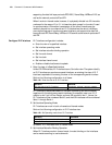
CT1/PRI interface configuration includes:
■ Enter the view for a specified interface
■ Bind the interface to be channel sets
Operation Command
Display the operating status of the CE1/PRI
interface
display controller e1
interface-number
Display the operating status of the channel set
or pri set
display interfaces serial
interface-number:number